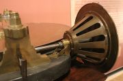
Dividing Engines, Florence, 1760s


Precisely divided scales, straight and circular, were of vital importance for instruments used in navigation, surveying astronomy, and physics.
The Museo Galileo (Florence) have on display a line-dividing engine (macchina per dividere le rette) and a circle-dividing engine (macchina per dividere i cerchi) made at the Florence workshops of the Imperial and Royal Museum of Physics (Regio Museo di Fisica Firenze).
The line dividing engine is stated to have been made in the second half of the 18thC., and the circle dividing engine in 1762. The validity of the 1762 date will be examined below.
Reference to photo L4 shows a number of features which appear unrelated to the dividing mechanism seen in the other photos of the linear dividing engine. In the general view (photo L1) the small four-legged elevated platform has no evident functional connection, and shows less sophisiticated workmanship, compared with the rest of the machine. A probable explanation follows:-
In the 1760s the Duc de Chaulnes (1714-1769) designed a linear dividing engine and a circular dividing engine. These were described in his 'Nouvelle méthode pour diviser les instruments de mathematique et d'astronomie' published in 1768.[1]. The 'elevated part' of the Florence machine is very closely comparable with the Duc de Chaulnes' machine illustrated in his Plate IX (reproduced here).
On the Duc's machine the scale to be divided was attached to a long, slender copper (brass?) bar running in a groove in the engine's table. On the museum's machine, this bar appears to have been replaced by wood. A pair of weighted cords attached to long bar passed over pulleys, and these can be seen in photo L6. Attached to the top of the long bar was a shorter brass bar with a rack cut on its left hand edge, and this engaged with gear teeth cut in the rim of a horizontal disc (Plate IX). This disc was rotated by a small worm (visible in photo L6) turned by a hand crank. In the background of photo L6 will be seen two brass bars, and the right hand bar has a rack cut in one edge. It is possible that this is the rack bar, reassembled in the wrong position. In photo L6, near the corner furthest from the camera, is a small wooden pedestal equipped with a number of brass fittings. The Duc's illustrations show that this accommodated a telescope.
Plate IX shows a microscope. Maurice Daumas[2] suggests that the positioning of the workpiece, finely controlled by the worm and wheel driving the rack, was determined using a master scale attached to the long bar and viewed under the microscope. This might explain why the rack's teeth were relatively coarse. On the other hand the fact that worm drive is shown with a micrometer dial suggests that it could be used as the primary method of positioning.
The process of engraving (scoring) the divisions on the workpiece was done using a complicated mechanism, attached to the table by four screws, and shown in the Duc's Plate IX. An identical attachment is also shown in the Duc's illustration of his circular dividing engine. We find the same apparatus fitted to the 1762 circle dividing engine seen in photo C6.
Part of the engraving mechanism's complexity arises from the ability to alter the angle at which the scribing arm moved across the workpiece. This would be useful for linear scales, but it is not obvious why the provision might be needed on the circular dividing engine. Perhaps it does suggest that the same engraving attachment was transferred between the two machines.
Considering some aspects of the engraving mechanism: The scriber's cutting arm was moved by catgut cord controlled by a small lever on a pulley (the museum's machine has a fusee-type chain instead of a cord); the amount of travel was limited by adjustable stops. The small brass bucket was weighted by lead to determine the force applied to the scriber.
The Duc's circular dividing engine, as described in 1768, is shown in Plate V. Source here. The principle is the same as that on the museum's '1762' machine, to the extent that the master wheel is turned by a worm, the worm spindle has a micrometer dial, and two microscopes were used. The museum's machine also has the Duc de Chaulnes' engraving mechanism. However, the museum's machine has a much larger master wheel, worm, and micrometer wheel than those shown on the Duc's detail drawings, the master wheel being about 4 times the diameter of the one illustrated by the Duc.
In view of the foregoing, while parts of both dividing engines are consistent with the Duc de Chaulnes' designs published in 1768, it is suggested that the machines were extensively altered at some later date.
Workmanship: Subjectively, the quality of workmanship appears higher on the circular dividing engine than on the scribing apparatus and on the linear dividing engine. The workmanship on the 'original' part of linear engine appears inferior to the rest.
See Also
Sources of Information
- ↑ [1] 'Nouvelle méthode pour diviser les instruments de mathematique et d'astronomie', by M. le duc de Chaulnes. Author: Albert d'Ailly, Michel-Ferdinand d' (1714-1769 ; duc de Chaulnes), 1768. Stated to be in the public domain.
- ↑ 'Scientific Instruments of the 17th & 18th Centuries and their Makers' by Maurice Daumas, translated by Dr Mary Holbrook, Portman Books, 1972

