Almond Feeder Aqueduct: Difference between revisions
No edit summary |
No edit summary |
||
| Line 9: | Line 9: | ||
[[Image:ImJD 2019 Almond Feeder Aqueduct8.jpg|thumb|9.]] | [[Image:ImJD 2019 Almond Feeder Aqueduct8.jpg|thumb|9.]] | ||
Cast iron aqueduct and footbridge carrying a feeder channel for the Union Canal, and a footpath, over the River Almond, in the picturesque Almond Valley, near Livingston, west of Edinburgh. | Cast iron aqueduct and footbridge carrying a feeder channel for the [[Union Canal]], and a footpath, over the River Almond, in the picturesque Almond Valley, near Livingston, west of Edinburgh. | ||
Constructed in 1822 by [[Craven, Whitaker and Nowell]]. Engineer: [[Hugh Baird]]. Maker of iron castings not identified. | Constructed in 1822 by [[Craven, Whitaker and Nowell]]. Engineer: [[Hugh Baird]]. Maker of iron castings not identified. | ||
| Line 17: | Line 17: | ||
'''DETAILS''' | '''DETAILS''' | ||
Photo 4 shows the modern footway over the aqueduct. | Photo 4 shows the modern footway over the aqueduct. Prior to its installation there were no handrails, and pedestrians walked on cast iron grids whose width was two-thirds that of the trough. | ||
The design of the cast iron bridge structure is elegant and well thought-out. Photos 1 & 3 show that the sides of the bridge structure and aqueduct walls comprise a series of wedge-shaped cast iron panels, bolted together at their radial flanges. | The design of the cast iron bridge structure is elegant and well thought-out. Photos 1 & 3 show that the sides of the bridge structure and aqueduct walls comprise a series of wedge-shaped cast iron panels, bolted together at their radial flanges. | ||
| Line 23: | Line 23: | ||
Transverse bracing is provided at the top of the arches by a series of diagonally-braced rectangular cast iron frames (see photos 2 & 6). The members are of T section. Bolted to the top surface of the arch is a series of solid iron castings whose cross section is apparent in photo 7. These should butt together to take compressive forces in the top chord. | Transverse bracing is provided at the top of the arches by a series of diagonally-braced rectangular cast iron frames (see photos 2 & 6). The members are of T section. Bolted to the top surface of the arch is a series of solid iron castings whose cross section is apparent in photo 7. These should butt together to take compressive forces in the top chord. | ||
Photo 8 shows the floor of the trough, made of flanged cast iron plates, The transverse joints of the floor | Photo 8 shows the floor of the trough, made of flanged cast iron plates, The transverse joints of the floor are staggered relative to the vertical joints between side plates. | ||
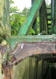
Photo 9 shows transverse brackets | Photo 9 shows transverse brackets whose role is to support the sides of the trough and to support the footway. | ||
A number of fractures have been repaired by bolting on fishplates. | A number of fractures have been repaired by bolting on fishplates. | ||
Revision as of 15:35, 15 June 2019
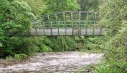
Cast iron aqueduct and footbridge carrying a feeder channel for the Union Canal, and a footpath, over the River Almond, in the picturesque Almond Valley, near Livingston, west of Edinburgh.
Constructed in 1822 by Craven, Whitaker and Nowell. Engineer: Hugh Baird. Maker of iron castings not identified.
80 ft span, 6 ft wide. Depth of water: 3 ft.
DETAILS
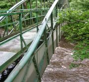
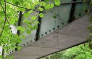
Photo 4 shows the modern footway over the aqueduct. Prior to its installation there were no handrails, and pedestrians walked on cast iron grids whose width was two-thirds that of the trough.
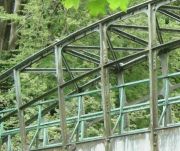
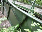
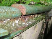
The design of the cast iron bridge structure is elegant and well thought-out. Photos 1 & 3 show that the sides of the bridge structure and aqueduct walls comprise a series of wedge-shaped cast iron panels, bolted together at their radial flanges.
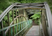
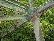
Transverse bracing is provided at the top of the arches by a series of diagonally-braced rectangular cast iron frames (see photos 2 & 6). The members are of T section. Bolted to the top surface of the arch is a series of solid iron castings whose cross section is apparent in photo 7. These should butt together to take compressive forces in the top chord.
Photo 8 shows the floor of the trough, made of flanged cast iron plates, The transverse joints of the floor are staggered relative to the vertical joints between side plates.
Photo 9 shows transverse brackets whose role is to support the sides of the trough and to support the footway.
A number of fractures have been repaired by bolting on fishplates.

