Difference between revisions of "Early Lathes"
| (2 intermediate revisions by the same user not shown) | |||
| Line 213: | Line 213: | ||
==Power== | ==Power== | ||
In the 18thC most lathes were driven by leg power, whether by | In the 18thC most lathes were driven by leg power, whether by using a spring-loaded cord wound the workpiece, or by driving the spindle by a treadle via a flywheel. Larger lathes could be driven by a 'large wheel' turned by manpower, or by water power. | ||
Towards the end of the 18thC, | Towards the end of the 18thC, steam power started to be utilised, especially when lathes migrated from a turner's own premises to a factory setting, with the advent of large textile mills (which often made their own machinery). We find this advert in Manchester in 1795:- | ||
'To Spinners, and Turners in Wood and Metal. Any Person in the above Business, wishing to engage turning for Mules or Preparations for Mules, or common Carding for Jennies, or Turners’ Laths, in Wood, Brass, or Iron, may be accommodated with Power and Convenience, from a Patent Steam Engine, with any Speed, and private Rooms, if required, and every other Accommodation requisite, in a Part of the Town of Manchester where there is as great a Choice of Hands as can desired, and also Plenty of Cottages on the Premises, now untenanted, with others now building, and nearly in a finished State; not more than five Minutes Walk from the Market-place. For further Particulars direct to No.4, to be left at the Post Office till called for.' <ref>Manchester Mercury - Tuesday 15 December 1795</ref> | 'To Spinners, and Turners in Wood and Metal. Any Person in the above Business, wishing to engage turning for Mules or Preparations for Mules, or common Carding for Jennies, or Turners’ Laths, in Wood, Brass, or Iron, may be accommodated with Power and Convenience, from a Patent Steam Engine, with any Speed, and private Rooms, if required, and every other Accommodation requisite, in a Part of the Town of Manchester where there is as great a Choice of Hands as can desired, and also Plenty of Cottages on the Premises, now untenanted, with others now building, and nearly in a finished State; not more than five Minutes Walk from the Market-place. For further Particulars direct to No.4, to be left at the Post Office till called for.' <ref>Manchester Mercury - Tuesday 15 December 1795</ref> | ||
==Towards Rational Designs== | ==Towards Rational Designs== | ||
| Line 245: | Line 245: | ||
American lathes of the early-mid 19th century generally shared a number of distinctive and curious features. Those same features remained popular for a very long period, with few makers being willing to diverge from this conformity, despite their apparent shortcomings. Given the way that the USA would come to lead in machine tool innovation in the second half of the century, this widespread adherence to questionable features in the first half is curious, and worthy of detailed consideration. | American lathes of the early-mid 19th century generally shared a number of distinctive and curious features. Those same features remained popular for a very long period, with few makers being willing to diverge from this conformity, despite their apparent shortcomings. Given the way that the USA would come to lead in machine tool innovation in the second half of the century, this widespread adherence to questionable features in the first half is curious, and worthy of detailed consideration. | ||
The typical American lathe of the first half of the 19th century had a number of features which | The typical American lathe of the first half of the 19th century had a number of features which are inimical to both rigidity and ease of use. They often had wooden beds fitted with metal guide strips. These guide strips tended to be of narrow vee form, whose acute angle suggests high frictional forces (due to wedging action), a situation not helped by the weighted carriage (saddle) concept. | ||
On these lathes, a heavy weight was suspended from the carriage. Its presence, hanging below the carriage, had a significant negative consequence - it precluded the use of intermediate stiffening cross members between the two beams of the bed. | On these lathes, a heavy weight was suspended from the carriage. Its presence, hanging below the carriage, had a significant negative consequence - it precluded the use of intermediate stiffening cross members between the two beams of the bed. | ||
The typical carriage had two main parts, the upper part being arranged to | The typical carriage had two main parts, the upper part being arranged to tilt using a jacking screw to alter the tool height. Viewed in plan, the two parts of the carriage were T-shaped castings (or T-shaped on top, and H-shaped below). They were of rather slender width. Modest in thickness (depth), too: having to allow for the thickness of two castings and a gap between them was paid for by the penalty of reduced swing over the carriage. Some makers compensated to some extent by cranking the castings downwards in the middle. | ||
The upper T-shaped carriage casting was the cross-slide. Guidance on the front side relied on small, narrow ridges. These were short and provided very limited transverse movement. This limited the ability to take broad facing cuts without repositioning the tool. The slenderness of the cross-slide also limited its torsional stiffness, important when boring a workpiece with a long overhanging tool. | The upper T-shaped carriage casting was the cross-slide. Guidance on the front side relied on small, narrow ridges. These were short and provided very limited transverse movement. This limited the ability to take broad facing cuts without repositioning the tool. The slenderness of the cross-slide also limited its torsional stiffness, important when boring a workpiece with a long overhanging tool. | ||
| Line 255: | Line 255: | ||
Rapid adjustment of tool height seemed to be more important than rigidity on US lathes, and the concept seems so fraught with drawbacks that there must be more behind it than meets the eye of the 21st century observer. A possible explanation is offered [https://www.practicalmachinist.com/vb/antique-machinery-and-history/pratt-whitney-lathe-cl-316291/ here] <ref>[https://www.practicalmachinist.com/vb/antique-machinery-and-history/pratt-whitney-lathe-cl-316291/] Practical Machinist forum: post by 'Joe in NH', 16 Feb 2016</ref>, which suggests that for several decades lathe operators in the USA were disadvantaged in the availability of satisfactory steel lathe tools. The US tools would have demanded more frequent reshaping and regrinding, making quick adjustment desirable. | Rapid adjustment of tool height seemed to be more important than rigidity on US lathes, and the concept seems so fraught with drawbacks that there must be more behind it than meets the eye of the 21st century observer. A possible explanation is offered [https://www.practicalmachinist.com/vb/antique-machinery-and-history/pratt-whitney-lathe-cl-316291/ here] <ref>[https://www.practicalmachinist.com/vb/antique-machinery-and-history/pratt-whitney-lathe-cl-316291/] Practical Machinist forum: post by 'Joe in NH', 16 Feb 2016</ref>, which suggests that for several decades lathe operators in the USA were disadvantaged in the availability of satisfactory steel lathe tools. The US tools would have demanded more frequent reshaping and regrinding, making quick adjustment desirable. | ||
Moving now to the headstocks and tailstocks, these were broad for stability, but the wide span between the support feet - often exacerbated by having four slender legs and small feet - caused another loss of rigidity. | Moving now to the headstocks and tailstocks, these were broad for stability, but the wide span between the support feet - often exacerbated by having four slender legs and small feet - caused another loss of rigidity. The feet were presumably small in order to minimise the amount of chipping and filing. | ||
The carriage was moved along the bed by a chain or by a moving rack. The chain was powered from the lathe spindle via gearing or moved manually using a large handwheel located alongside the headstock. | The carriage was moved along the bed by a chain or by a moving rack. The chain was powered from the lathe spindle via gearing or moved manually using a large handwheel located alongside the headstock. | ||
| Line 269: | Line 269: | ||
Examples of these old lathes were often featured in US production engineering magazines. Their date of construction was often speculative, but an example built by Nathaniel Wiley at Watertown seems to have been positively dated to 1830.<ref>[https://babel.hathitrust.org/cgi/pt?id=mdp.39015080135638;view=1up;seq=85;size=150] Machinery, November 1897, p.83</ref>. It had several owners before being put out to grass in 1889. See photo above (the large handwheel is missing). | Examples of these old lathes were often featured in US production engineering magazines. Their date of construction was often speculative, but an example built by Nathaniel Wiley at Watertown seems to have been positively dated to 1830.<ref>[https://babel.hathitrust.org/cgi/pt?id=mdp.39015080135638;view=1up;seq=85;size=150] Machinery, November 1897, p.83</ref>. It had several owners before being put out to grass in 1889. See photo above (the large handwheel is missing). | ||
A well-preserved example is described and illustrated [http://vintagemachinery.org/photoindex/detail.aspx?id=20448 here]<ref>[http://vintagemachinery.org/photoindex/detail.aspx?id=20448] vintagemachinery.org</ref> and [https://www.practicalmachinist.com/vb/antique-machinery-and-history/bement-s-early-years-peterborough-new-hampshire-link-my-1830s-lathe-291020/ here] <ref>[https://www.practicalmachinist.com/vb/antique-machinery-and-history/bement-s-early-years-peterborough-new-hampshire-link-my-1830s-lathe-291020/] Practical Machinist forum - post by 'Humphrey Machine 2014</ref>. It has been attributed to [[Moore and Colby]], evidently between 1833 and 1837. It has a rack feed, and each beam of its bed is laminated from eight pine boards. An iron weight of >150 lbs hung from the carriage. Interestingly, the lathe had a leadscrew, although it is not clear how this was accommodated. | A well-preserved example is described and illustrated [http://vintagemachinery.org/photoindex/detail.aspx?id=20448 here]<ref>[http://vintagemachinery.org/photoindex/detail.aspx?id=20448] vintagemachinery.org</ref> and [https://www.practicalmachinist.com/vb/antique-machinery-and-history/bement-s-early-years-peterborough-new-hampshire-link-my-1830s-lathe-291020/ here] <ref>[https://www.practicalmachinist.com/vb/antique-machinery-and-history/bement-s-early-years-peterborough-new-hampshire-link-my-1830s-lathe-291020/] Practical Machinist forum - post by 'Humphrey Machine 2014</ref>. It has been attributed to [[Moore and Colby]], evidently between 1833 and 1837. It has a rack feed, and each beam of its bed is laminated from eight pine boards. An iron weight of >150 lbs hung from the carriage. Interestingly, the lathe had a leadscrew, although it is not clear how this was accommodated. | ||
A rack-type lathe having a stamped date of 1833 and the engraved initials N.M. is shown in detail [https://www.practicalmachinist.com/vb/antique-machinery-and-history/early-watertown-ny-lathe-353097/ here] <ref>[https://www.practicalmachinist.com/vb/antique-machinery-and-history/early-watertown-ny-lathe-353097/] Post in the Practical Machinist website by 'enginebill', July 2018</ref>. Back gear was added to theheadstock at some later date. | |||
Joseph Wickham Roe<ref> 'English & American Tool Builders' by Joseph Wickham Roe, 1916. </ref> is strangely quiet on the matter of this type of American lathe. The sole relevant mention is in reference to machines from one maker, Samuel Flagg, whose lathes are described as 'light and crude, with a wooden bed, wrought-iron strips for ways, chain-operated carriage, and cast gears.....'. | Joseph Wickham Roe<ref> 'English & American Tool Builders' by Joseph Wickham Roe, 1916. </ref> is strangely quiet on the matter of this type of American lathe. The sole relevant mention is in reference to machines from one maker, Samuel Flagg, whose lathes are described as 'light and crude, with a wooden bed, wrought-iron strips for ways, chain-operated carriage, and cast gears.....'. | ||
Revision as of 08:36, 10 July 2020






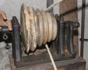
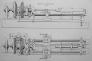

Introduction
Lathes have been in use for over 2000 years (for turning spindle whorls and bracelets, for example), but their evolution was remarkably slow.
Successful turning demanded a high level of skill and effort on the part of the turner, until the slide lathe started to find wider acceptance, c.1800. On the slide lathe, the tool is guided along the workpiece by slideways built into the lathe, rather than relying on hand-held tools. Movement of the guided toolholder along the slideways was effected manually or automatically using a leadscrew, rack and pinion or chain.
Slow Development
No great ingenuity was required to develop slide lathes, and few early lathe developments would warrant the word 'invention'. Rather, their acceptance resulted from the maker's ability to construct a lathe with the required standard of accuracy, usability, and durability.
In fact the development of machine tools in general was remarkably slow, especially as they were needed to construct the new wonders of the age, particularly textile machinery, a field in which some of the most ingenious engineers were deeply engaged. Notable participants who excelled in both fields, who did advance the technology of machine tools, included Jacques de Vaucanson, Richard Roberts, Matthew Murray, and Fox of Derby.
The slow development evidently partly reflects limited demand rather than lack of capability. More sophisticated lathes would only be wanted by industrialists if they could do the work more cheaply or more accurately than by the traditional methods. A lathe could readily be made self-acting, but an operator still had to stand in attendance. Economics would demand that the operator could work several machines at the same time, or allow the work to be done by cheaper labour. However, there was surely an incentive on the part of the turners themselves to have a mechanised alternative to the sheer hard work involved in paring metal off a rotating workpiece with a hand-held tool.
Another barrier was the difficulty in accurately making long, straight guiding surfaces, pending the arrival of another late developer - the planing machine. Even more fundamental in the 18thC. was the availability of large pieces of good quality wrought iron.
Another possible factor in the minds of potential purchasers is that although a self-acting slide lathe might be theoretically ideal for producing long, straight cylindrical surfaces, hand finishing would almost certainly be required to obtain a surface sufficiently smooth for, say, piston rods.
A factor in the growing appeal and acceptance of self-acting lathes was their ability to cut screws accurately, consistently, and relatively cheaply.
Away from the hurly-burly
It is noteworthy that by far the most sophisticated early lathes were not made for ordinary industrial production: they were used for producing scientific instruments (e.g. the screwcutting machines of Jesse Ramsden), clock and watchmaking, or for the amusement of rich clients (ornamental turning lathes). By far the most sophisticated early machine tools were clockmakers' wheel cutting machines, ornamental turning lathes and a version thereof used for copying medallion designs. Andrey Nartov in Russia produced remarkably advanced versions of these machines in the early 18thC. Some have survived in the Hermitage in St. Petersburg. Another was presented to a French gentleman by Peter the Great in 1717, and is on display in the Musee des Arts et Metiers in Paris.
Earliest Identified Makers
Attempts to assign priority to any particular aspect of early industrial lathe design are often futile. Surprisingly little is known about early slide lathes, dates of construction, or their makers, apart from some notable surviving examples, descriptions, or illustrations, including the products of Andrey Nartov, Jacques de Vaucanson, Senot, Jesse Ramsden, Henry Maudslay, Richard Roberts, and Joseph Clement.
Vaucanson's Lathe
Vaucanson's lathe of c.1751, on display at the Musee des Arts et Metiers, is a remarkably early example of a true industrial lathe, of all-metal construction. The carriage was guided by accurately-made prismatic guide bars and moved by a leadscrew of fine pitch (turned by a hand crank). The workpiece was turned between centres, presumably driven by a belt round the workpiece or on a pulley attached to a mandrel carrying the workpiece.
It was by no means a versatile machine, being made specifically for turning parallel calender rolls with a maximum length of approximately 1 metre. It could potentially be used to machine shorter workpieces, but this would involve moving and resetting one of the dead centres (there is no tailstock as such, and neither of the supports for the centres is positively guided to maintain a precise relationship with the carriage guides during repositioning).
Note: 'Centres' in this context refers to the accurately-machine steel or iron points used to locate and support one or both ends of the workpiece during turning.
Senot's Lathe
Senot's lathe of 1795, also on display at the Musee des Arts et Metiers, is an all-metal screwcutting lathe. It has a large diameter square-threaded leadscrew driven from the spindle by change gears, thus allowing threads of different pitches to be cut. It has a long iron bed which, unlike Vaucanson's lathe, unites and accurately guides the headstock, tailstock and carriage. It was a much more versatile machine than Vaucanson's, but even so, its utility was limited. It was designed for turning parallel cylindrical surfaces and for screwcutting, but the lack of a cross slide and the absence of manual traversing for the carriage were very restrictive.
The Compound Slide Rest
On the earliest industrial slide lathes the tool was positively guided in just one axis, parallel to the axis of the lathe spindle. Then came additional positive guidance in the direction normal to the axis (the cross slide). The next improvement was the mounting of an additional slideway on the cross slide. This was either set to move parallel to lathe axis, or was pivoted to allow it to be swivelled at an angle to the axis.
A very sophisticated swivelling slide is found on the 1780 rose engine of Mercklein, displayed in the Musee des Arts et Metiers. No doubt there are earlier examples to be found.
Joseph Bramah's c.1794 lathe had a compound swivelling slide rest. Some sources attribute the design to Bramah and the construction to Henry Maudslay. The design is curious, and appears to be deficient with regard to rigidity. The slide rest was combined with the tailstock, and the assembly clamped onto a bar bed with an inverted Vee shaped top. Rolt suggests that the lathes, or the slide rests, were made for sale.
Henry Maudslay
There is little doubt that Henry Maudslay deserves credit for screwcutting slide lathes finding widespread acceptance in engineering production. This contribution has often been misinterpreted by commentators to claim that Maudslay invented the slide lathe. Maudslay synthesised the key elements of precision lathe design and produced machines for industrial manufacturing purposes. Joshua Field stated that Maudslay 'introduced the general use of the sliding rest throughout his manufactory' [1].
Maudslay's small 'c.1800' lathe, displayed in the Science Museum, was probably made between 1797 (when he left Bramah) and 1800 (when Marc Brunel sought his services). It had a carriage guided by accurate V-ways (previously applied by Vaucanson); a dovetailed cross slide (similar to that used on Lord Macclesfield's lathe of c.1740); a micrometer dial on the cross slide leadscrew (Mercklein's 1780 O.T. lathe), a leadscrew with change wheels for screwcutting (Henry Hindley, c.1740, Senot, 1795), and an accurately guided tailstock centre. Senot's screwcutting lathe of 1795 already had most of these features, but its toolholding arrangement was not ideal, and Maudslay's tailstock centre arrangement was arguably superior in principle, the centre point being machined on the end of a plain cylindrical bar located in the tailstock. On Senot's lathe (and Vaucanson's much earlier lathe), the centre was machined on the end of the tailstock's screwed spindle, making it more difficult to ensure concentricity when machining or remachining the point.
Maudslay produced some special-purpose lathes for the Portsmouth Block Mills. One type was used for turning wooden treenails and coaks. Its main point of interest was the use of a rack and pinion to traverse the carriage. Drawing from Simon Goodrich archive here [2]. The other type of lathe was used for turning iron pivot pins for pulley blocks. 1804 drawing here. This had a number of interesting features. The tailstock was carried on a triangular bar, while the carriage was guided by dovetail ways. The cutting tool was of the tangential type, held in the triangular cross slide. Of particular interest is the fact that the lathe was partly self-acting. The carriage leadscrew was driven from the lathe spindle by a belt drive acting through a worm and wheel. On reaching the end of travel, a trigger was released by the carriage, which dropped the worm out of engagement. There were presumably several such lathes, allowing one operator to set up and start the others while the first was cutting.
Early References
At some point the more sophisticated lathes became known as engine lathes. There is no exact definition, but the term generally came to be applied to machines of all-metal construction, power-driven, self-acting - at least in the longitudinal direction - and equipped for screwcutting. However the term 'engine lathe' was earlier applied to a class of machines used for producing decorative patterns, non-circular shapes, etc. These machines are now more commonly known as ornamental turning lathes, or rose engines, but the term 'engine turned' is still used for machine-cut patterns on watches, jewellery, etc. There were also references to engine lathes in the industrial context. Some examples follow.
In 1767 James Fox (1760-1835) was advertising a range of products which included '... all kinds of engine, oval and common lathes.... He also performs every branch of Turning, on Wood, Ivory, and the different Kinds of Metal, in Engine, Oval, or Common Lathes.'[3].
1786 advert: ' 'To be SOLD by AUCTION, ..... at the Factory of John Rollason ..... ALL that well got up Cotton Machinery, .... exceeding neat Engine Lathe, Fluting Engine, and Several other Lathes, Machinery, &c. belonging the Cotton Manufactory…...'
1790 Advert: 'On the premises at Penley-hall, near Hanmer, in Flinthire, .... effects of Mrs. Dymock, of Penley-hall aforefaid ..... a large engine lathe, and a set of tools to ditto ; a grinding lathe, with seven stones to ditto....' [4]. It is more likely that the engine lathe was an ornamental turning lathe than an industrial lathe.
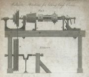
An early example of a heavy-duty industrial lathe having a tool guided in the 'X' and 'Y' planes was constructed by Jan Verbruggen at Woolwich Arsenal. The principal use of the water-powered machine was for boring cannon barrels, but it was also equipped for turning plain parts of the outer surface of the barrel. See illustration above, from Wikipedia, where higher resolution versions may be found[5]. It is entirely possible that Henry Maudslay saw this lathe during his time at Woolwich Arsenal.
From the early 19th century we find passing mentions of early industrial slide lathes in sale notices. Many were used in the production and maintenance of textile machinery. Vast quantities of spindles and rollers were required for spinning machinery. Textile printers required accurately produced rollers. Whether they were inspired by Senot or Maudslay, we do not know, but given the timing, the high demand, and the remarkable ingenuity of the textile machine designers, it is quite likely that they were designed and constructed independently.
Examples:-
1800 Auction sale - '... on the Premises in Dale-street, Manchester, lately used by Mr. Grocott, as a Turner's shop ALL the UTENSILS, necessary for carrying on the said Trade, consistng of three lathes, wheels and spindles, large shaft, copper bowls, iron rests and maundles, sliding engine to turn metal, quantity of print rollers, old iron, teagle, rope. &c. ....[6]. The 'sliding engine to turn metal' was presumably a slide lathe.
1802 An advert for the sale of cotton mill equipment, formerly the property of Peter Atherton, included one foot Lathe with 4 square steel bars. [7]
1802 Advert: 'To Machine Makers, Roller Turners, and others. To be SOLD by AUCTION, .... at Mr. Reynolds Factory, Balloon street, Manchester. Three capital Slide Lathes, for Roller Making - these Laths are made upon an improved plan to slide themselves and likewise flute as well as turn, and are made to take up little room ; also Two Spacing Laths for turning iron, &c, with two pair of Screw Stocks, with a excellent set of Taps and Dies, ...' [8]. Spacing lathes: used to turn the stepped diameters on spinning rollers?
1804 Auction notice: '... at Mrs. Gatley's Factory, Knot Mill, SEVERAL SPACING LATHES, two Fluteing Engines and Turning Tools, with a good pair of Bellows, Anvil and quantity Tools, Press, Drill, &c, fit for Roller Makers....'[9]
1804 Sale of equipment at Crumpsall Mills, Manchester, included 'NINE SPACING LATHES, and Lathes Frames, Slide ditto, Fluting Engines.... Likewise large quantity Wrought Iron for Rollers, of the best quality.' [10]
Manchester, 1805: 'One excellent clock maker’s cutting engine, one double fluting engine, one slide lathe new, .... two pair of excellent stock dyes and taps, several screw plates, six turners lathe spindles and headstocks, two lathe frames and wheels,....'[11].
In 1805 Jacob Goodier advertised for sale 'Two Slide Lathes, 5 spacing lathes, 4 fluting engines; quantity iron rollers, .....'[12].
1806 Advert: 'To Ship-Owners, Surveyors, Pump and Engine-makers, Braziers, Founders, and Others.
By Messrs. Fairbairns on the Premises No. 12, Dean-street, Soho-square, ..... The valuable STOCK and IMPLEMENTS in TRADE, of a Metallic Pump and Engine-maker; comprising a variety of engines and pumps .... five capital turning lathes, with apparatus for cutting screws and turning metal flat plates, round and square; four metal planes, ...... a clock-maker’s cutting engine..... [13]
1806 Advert: 'Sale by auction ..... (By order of the assignees of Richard Ollis, bankrupt). .... a number of spacing and slide lathes, several fluting engines, .... about twenty sets of bottom rollers, from fourteen to sixteen inches, with top rollers, belonging. [14]
1806: Simon Goodrich (of the Navy Board) wrote to Samuel Bentham (Admiralty) about machinery being exported to Russia. Some of the machinery was supplied by Fox of Derby, including a large boring, turning and screw cutting lathe, at £296, and a slide lathe for cutting screws, for £86.[15].
1808 Advert: 'SALE by AUCTION, .... at a factory at Shooter's Brook, London Road, [Manchester] A CAPITAL patent steam engine, ten horses' power; a large quantity shafts and geering for same ; new and complete mill for rolling lead, capable of rolling the width of six feet four inches; a machine for drawing out patent lead pipes, three slide lathes for metal turning, with all descriptions of tools and utensils for working the same; a small boring mill, four spindle lathes, ....'[16]
In 1809 the sale of effects of Ridgway and Stott of Manchester in 1809 included 'sundry slide and other lathes for turning iron and copper bowls, rollers, &c.'[17].
1809 'a Slide Lathe for turning Iron or Copper Rollers' was included in the sale of equipment of Smith and Unsworth of Manchester.
Early lathes are often found in museums. Only very rarely is the date of construction known, even approximately. It is unwise to attempt to assign a date based on the form of construction, as primitive features, such as wooden beds, continued to be adopted long after more sophisticated designs appeared.
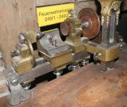
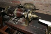
The Deutsches Museum in Munich does a fine job of presenting a range of machine tools from the 18th century up to the present day. Their earliest dated example is a lathe stamped 'Paris 1741' and once owned by ebony artist P.-F. Daneau[18] (see photo). At first sight it appears highly sophisticated for its age, with the main elements being constructed of metal and made to a very high standard. Screws of five different pitches could be cut by engaging a key with one of five screwed portions of the spindle, which would advance the spindle axially as it rotated. A sixth key fixed the position for normal turning. This principle had been invented many years previoulsy. On this lathe, it was still necessary to hold the cutting tool against the work by hand. A very interesting feature is that in addition to being treadle-driven, it was also provided with a 'clockwork' drive, using a mainspring housed within a brass drum over which the drive belt passed.
A much more complex lathe in the Deutsches Museum was made by J. Shega of Vienna, c.1767 (see photo). It is a Kunstdrechslerbank (ornamental turning lathe, engine turning lathe or rose engine). It was capable of cutting a variety of patterns and cutting screws, but again the cutting tool was hand-held.
It is probable that iron components for industrial lathes of the late 18th/early 19thC, namely headstocks with spindles, tailstocks, and tool rests were made for sale, leaving the purchaser to produce the wooden bed and drive arrangements. These parts were of relatively light construction, perhaps reflecting difficulties in transportation to remote places. One of the few known commercial makers of component parts of lathes is revealed in a 1775 advert: 'SALISBURY. TO be SOLD, an extraordinary good Lathe, (with or without a collar and manderil, and treadlewheel) with a large wheel on frame, very convenient for shifting, and has three counter-wheels on it. Enquire of John Mendum, at Sir Alexander Powell's. N.B. The collar and manderil were made the best makers in England, Messrs. Baily and Macartney.'[19]
Triangular Bar Beds
One form of construction which found favour within a fairly short window of time was the use of a bar bed of triangular section. First appearing in the mid 18th century, the type came to prominence in 1777 when Jesse Ramsden published a detailed description of his dividing engines and the two lathes with triangular bar beds which were used to cut the high precision screws.
Triangular bar beds were fairly widely used by the late 18thC, and probably fell out of favour in the second decade of the 19th century, although several makers in Germany favoured this style for much longer. Their wide acceptance was possibly influenced by the type being adopted and made available by the respected Henry Maudslay. Examples of Maudslay lathes can be seen in a number of museums. This c.1805 example in Australia, originally owned by Sir John Barton, is ascribed to Maudslay, Sons & Field. However, while the slide rest is fully consistent with Maudslay's design and construction, some other keys aspects, primarily the headstock and tailstock, are not Maudslay-like. The Henry Ford Museum in the USA has an example with a two-bar bed and a central leadscrew. Unusually, the carriage is held down by rollers pressing on the underside of the slideways. The lathe was gifted to the Ford Museum by Sir W. G. Armstrong, Whitworth and Co. Photographs here.
The triangular bed allowed the key components - headstock, tailstock and tool rest to be maintained in alignment, while the triangular form provided the easiest and most economical way of accurately manufacturing such a form of guidance by hand methods. Just the two upper faces needed to be made true, the quality of the underside being of little importance. Ease of hand production of the guiding surfaces was an important factor, given that the arrival of the planing machine was so surprisingly late. However, the triangular bar bed had limited stiffness due to its necessarily limited section size. A marked improvement came with the use of a pair of parallel bars, both guiding the same carriage. This appreciably increased the resistance to twisting and transverse deflection, but demanded very high standards of manufacture. Henry Maudslay made twin bar lathes for industrial production.
Note: The cross slide on Maudslay's lathes was a dovetailed casting incorporating two pillars through which the cutting tool was passed and clamped down by screws. This followed established practice, seen, for example on Lord Macclesfield's c.1740 ornamental turning lathe. Illutration here[20]
Having observed that the triangular bed allowed the headstock, tailstock and tool rest to be maintained in alignment, it might be wondered why this was so important on lathes used with tool that were hand-held and not guided by slides. The arrangement allowed the components to be locked in position rigidly, and quickly. Rigidity was important given the higher forces imposed when turning metal. When holding a relatively long workpiece, driven by the headstock spindle, rather than by wrapping a cord round the workpiece, it was desirable that the axis of the spindle and the tailstock centre should be accurately aligned. The triangular bed facilitated good alignment. On some examples the headstock comprised two separate castings, and their alignment depended on the triangular bed.
Henry Maudslay was by no means the first adopter of triangular bar beds, and neither was he the only prominent producer of industrial calibre examples. Matthew Murray used them on his large cylinder boring machines. They were also noted by Simon Goodrich as being used for the slideways of Matthew Murray's self-acting roller fluting engines when he visited Murray's works in January 1803. The earliest recorded example of a triangular bar bed lathe was made by Henry Hindley before 1758. He in turn influenced John Smeaton.
1796 Advert for sale of a triangular bar bed lathe: 'TURNING LATHE. TO BE SOLD, (the Property of a Gentleman,) A VERY COMPLETE LATHE, on triangular Steel bar, with apparatus for Screws and Oval Engine. Enquire Miss. Leventhorpe's, in the Square.[21]
There is a good discussion of triangular bar bed lathes here.
An 1813 engraving here, showing a simple treadle lathe, is intriguing because it shows an iron bed which appears to have two rectangular/triangular rails, joined together at the ends.
Screwcutting Machines
A specialised form of lathe was used primarily or solely for cutting large screws.
Highly sophisticated machines were in use by the mid 18th century for cutting small high precision screws for scientific instruments, clocks and watches. Fusee-cutting engines were particularly interesting, because they cut a thread on a hyperbolic profile.
A number of inventors introduced screwcutting machines in the form of specialised lathes having the carriage traversed by a leadscrew driven from the spindle via gears. There is no reason to assume that these were originated by one person and copied down the centuries, as there are not that many alternative ways of cutting accurate screws. Andrey Nartov constructed such a machine in 1718. The available illustrations leave much to be desired, but a hand crank is shown attached to a flywheel, driving the workpiece and the tool carriage's leadscrew via gears. The main frame and the handwheel were probably made of wood, with the slideways probably of metal. An interesting feature is the toolholder: the cutting tool is held in a pivoting arm and pulled into contact with the workpiece by a wingnut on a screw.
An early British example of a screwcutting machine is revealed by an advert from 1738. Unfortunately we know nothing about its construction. 'ALL Sorts of Iron Screws, from two Inches and a Half, to five Inches Diameter and upwards, the Threads whereof are cut by an Engine with great Exactness, are Made and Sold, at very reasonable Prices, by ROBERT BOWMAN, Anchor-Smith, at Whitehaven in Cumberland.'[22]
In 1741 Henry Hindley showed John Smeaton his lathe for cutting accurate screws. He described it as a 'chock' (chuck?) lathe, and Hindley showed him 'the method employed to make the threads of the screw equiangular with the axis, that is, to free the screw from what workmen term drunkenness; and also shewed me how, by the single screw of his lathe, he could cut, by means of wheel work, screws of every necessary degree of fineness (and, by taking out a wheel, could cut a left-handed screw of the very same degree of fineness)...'.[23] [24]
1754 R. R. Angerstein described the machining of large iron press screws at Coalbrookdale[25]. His description and sketches show simple contrivances, and lack detail. The cast or wrought iron screw blanks were first turned in a simple lathe powered by a waterwheel, presumably using hand-held tools. The screwcutting was done in a wooden-framed machine driven by a hand crank. The blank was coupled to a master screw ('regulator') engaging with a nut in the second of five supports. The first support contained the cutting tool, evidently moved in and out by a leadscrew. The other three supports were for the crankshaft and flywheel, well-spaced to allow the assmbly of workpiece, master screw, and crankshaft to travel the requred distance. The reason for preferring hand power over water power in screwcutting was to facilitate the required repeated reversals of motion.
1764 The sale of the Busy Cottage ironworks in Newcastle included An Engine, moved by Water, for cutting Dyers and Pressers Screws, Slitting Mill Pillars, and for turning either large or small Work. Was this a very early power-driven industrial-scale screwcutting lathe? We can assume that the screws referred to are large and made of iron, being used for some process in the dyeing industry, for presses, and for rolling mills.[26]. See also below regarding Pickering's patent.
1765 Patent No. 829: '12th June 1765. 829. A grant unto George Pickering, of Busy Cottage, near the town and county of Newcastle-upon-Tyne, whitesmith, of his new invented method of making & compleating an iron screw for raising & lifting up timber, & other purposes therein mentioned; to hold to him, his execrs , admrs , & assigns, within England, Wales, & town of Berwick-upon-Tweed for the term of 14 years pursuant to the statute ; with a clause to inroll the same within 4 Kalendar months from the date hereof. Witness His Matie at Westmr, the 12 th day of June, in the year above. By writ, &c.'[27]
1770s Jesse Ramsden built two special-purpose screwcutting lathes to cut the 'endless screws' for his dividing engines. They each had the cutting tool held in a slide guided by a triangular bar. The first machine was used to cut the worm for his circular dividing engine. It was designed to produce a pitch in the workpiece 1% coarser than the leadscrew which guided the tool (i.e. to correct a 1% pitch error in the original screw). It did this by having change wheels of 198 and 200 teeth with an idler gear between them. His machine for cutting the screw for his linear dividing engine was very different. See illustration above[28].
1785 Advert: 'To be Sold by Auction, by order of the Assignee of Messrs. George and Samuel Daniell, bankrupts, at Pennygorred, near Cardigan, on Wednesday the 13th of July instant, All the TRADE of the said Bankrupts, of about thirty tons of bar and bolt iron, the tools and implements of the forges and mills, and a very excellent new engine for cutting screws for Standards, &c. for rolling-mills ; together with several pairs hard rolls, sundry hammers, anvils, &c., &c.'[29]
c.1795 Senot in France produced the precision machine described above, which could cut relatively large screws, using change wheels to cut a range of pitches. The carriage was permanently engaged with the leadscrew, and no means were provided for moving the cutting tool transversely independently of the leadscrew. See Senot's Lathe.
in 1798 David Wilkinson in the USA obtained a patent for a water-powered screwcutting machine, which he used to produce large iron screws. It could only cut screws with the same pitch as the leadscrew. A patent drawing of the machine exists, but it was produced about 40 years after the date of the patent. As drawn, the machine would have appreciable shortcomings in practical operation. An apparently novel feature was the use of a split nut to engage with the leadscrew. See David Wilkinson for more information about this machine, as illustrated in the post-patent drawing.
The Science Museum has on display two examples of screwcutting lathes by Henry Maudslay, dating from c.1800, one of these being a model. These lathes could cut a variety of pitches by using different leadscrews and/or change wheels. For more information, see Henry Maudslay: Machine Tools.
Messrs Gallimore of Sheffield were makers of large screws. Lardner described one of their turning and screwcutting in 1833 [30]. See illustrations. It was of all iron construction. The carriage slid on V-guides and was moved by chain drive. The pitch was determined by change wheels. Deflection of the workpiece by the force of the cutting tool was prevented by a support on the opposite side to the tool. There were several Gallimores who produced screws in Sheffield. The most likely candidates for this machine were John Gallimore (of Sheffield) or Josiah Gallimore or John and Josiah Gallimore. Lardner stated that 'Messrs. Gallimore had been noted for their manufacture of large screws, especially those used for elevating the breeches of cannon during the late war'. The Napoleonic wars ended in 1815.
The Encylopaedia Metropolitana included a drawing and description of a large screwcutting lathe at Woolwich Dockyard. The drawing, reproduced here, is dated 1834, and, incidentally was drawn by P. Barlow Jr. (Peter William Barlow?). Screws of any pitch could be cut by changing the ratio of the gear wheels on the spindle and on the leadscrews. There were two leadscrews, enabling cuts to be taken on each side of the workpiece. To cut internal threads, the nut or other component to be threaded would be bolted to the slide rest and a threading tool would be mounted on a rotating boring bar. The machine was also described in the Cyclopedia of Useful Arts published in 1854, where it is noted that the rear tool was intended to cut while the front tool was returning to the starting point on completion of its traverse, but this method 'does not produce very good results in practice'. It should be mentioned that Leonardo da Vinci's sketches included a screwcutting machine on the same principle, but presumably his sketches were not available to influence future technology.
The Encylopaedia Metropolitana also referred to a type of machine at Woolwich Arsenal for cutting original screws of any required pitch, and described it as 'One of the neatest and most perfect engines of this kind for short screws and taps .... constructed, and, we believe invented by the late Mr. Adam Reid.[31]. It appears that Reid's machine followed the principle of the fusee cutting machine (originally developed in France). The cutting tool was traversed by the action of an inclined plane moved by a rack and pinion, the pinion being fixed to the lathe spindle. Charles Holtzapffel notes that despite the length of the inclined plane (44"), the maximum size of screw that could be cut was limited to 1.6" diameter and 2.25" long.[32]
Missing Links
We have some clear information on specific lathes made for identified users, namely complex machines made at enormous expense for wealthy amateur turners, and sophisticated machines made to meet the scientific community's demand for accurate instruments.
At the industrial end of the spectrum, things are far less clear. We know that Henry Maudslay was very active in advancing industrial lathe design from the end of the 18thC. We have seen brief references to 'engine' and 'slide' lathes in use in industry from the 1790s, so we will consider what was happening in industrial production at that time.
Two 'boom' areas will be considered: textiles, and steam engines. Mention has already been made of the need for lathes (and fluting engines) to produce vast numbers of spindles, rollers and other components for textile spinning machinery. There is evidence that slide lathes were in use by 1800, and there would have been no difficulty in designing and producing them within the textile machinery industry. What is lacking is any tangible evidence to show what these machines looked like. It may simply be that they were too specialised, and too worn out, to be worth keeping.
In the field of steam engines, the late 18th century saw an increasing demand for accurately turned cylindrical components. One particular component which surely demanded the use of a slide lathe was the piston rod. These rods were several inches in diameter and several feet long. It seems likely that Matthew Murray had such lathes at work by the end of the 18th century, but information has not come to light. Boulton and Watt lagged behind Murray in their engine workshop capability, but in contrast to Murray's, good records have survived.
In April 1777 'a lathe for turning piston rods was set' up at Soho Works. In 1781 Boulton wrote to Watt suggesting setting up a workshop in Cornwall with 'a sockett plane to turn piston rods'.[33], which does nothing to clarify our understanding of the design of these lathes. We should probably not suppose that anything sophisticated was involved. The piston rod would have been finished by filing and honing in the lathe. It would need to be strong and reasonably powerful, with a range of speeds to allow for the operations of paring down towards the finished size, machining the details, and polishing. The addition of a compound slide would be highly advantagous, especially if there was a tapered portion to be machined to suit the piston. Regarding speeds, a Boulton & Watt document dated December 1801 refers to the piston rod lathe having speeds of 18, 38 and 60 rpm, with a proposal to change the speeds to 18, 30, 50, and 80 rpm.[34]. This 1895 photograph, taken at the Boulton and Watt Soho Foundry, shows what is clearly an early lathe with the addition of a somewhat more modern compound slide. It has a four speed spindle, and it is not impossible that this was used for turning piston rods.
Another source suggests that slide lathes were not adopted by steam engine makers until much later. John Farey credited Arthur Woolf with the introduction of slide lathes in this field: 'Such lathes were used by accurate mechanicians on a small scale, but had not been used by steam-engine makers. He also made a slide lathe for turning piston rods and other cylindrical work, which required very little skill or exertion of the workman...' [35]. John Farey was an important observer of early steam engine practice. He does not give us a timeframe for Woolf's adoption of slide lathes.
Note: Arthur Woolf was part of a 'critical mass' of ingenious mechanical engineers who so much to develop the field of precision engineering in the early 19thC. For a time, Woolf, Henry Maudslay and Joseph Clement worked with Joseph Bramah. Richard Roberts, Joseph Whitworth and other prominent engineers worked for Henry Maudsaly. Woolf was friendly with Matthew Murray.
Power
In the 18thC most lathes were driven by leg power, whether by using a spring-loaded cord wound the workpiece, or by driving the spindle by a treadle via a flywheel. Larger lathes could be driven by a 'large wheel' turned by manpower, or by water power.
Towards the end of the 18thC, steam power started to be utilised, especially when lathes migrated from a turner's own premises to a factory setting, with the advent of large textile mills (which often made their own machinery). We find this advert in Manchester in 1795:-
'To Spinners, and Turners in Wood and Metal. Any Person in the above Business, wishing to engage turning for Mules or Preparations for Mules, or common Carding for Jennies, or Turners’ Laths, in Wood, Brass, or Iron, may be accommodated with Power and Convenience, from a Patent Steam Engine, with any Speed, and private Rooms, if required, and every other Accommodation requisite, in a Part of the Town of Manchester where there is as great a Choice of Hands as can desired, and also Plenty of Cottages on the Premises, now untenanted, with others now building, and nearly in a finished State; not more than five Minutes Walk from the Market-place. For further Particulars direct to No.4, to be left at the Post Office till called for.' [36]
Towards Rational Designs
Towards the end of the 19th century, more or less standard forms of general purpose lathes were well established. They could be expected to be back-geared, to have compound slides, to be self-acting and capable of screwcutting, and have versatile arrangements for holding work. Lathes with these features, based on rigid iron box beds, were being produced for sale by a number of British makers from the second and third decades of the 19th century. Some examples are mentioned below.
Later, British lathes could often be obtained with gap beds to allow large diameters to be turned. The carriages were often designed to hold work for boring. The adjustable gibbed dovetail arrangement removed concerns about the carriage being lifted during the machining process. These features were appealing to jobbing shops. However, the provision of a gap bed necessitated moving the leadscrew further out from the lathe axis, and this imposed a twisting moment on the carriage.
Unfortunately, few early British engineering lathes escaped the wartime scrap drives. One survivor which appears ahead of its time is the 1817 machine produced by Richard Roberts of Manchester, displayed in the London Science Museum.
Remarkably advanced examples were made by Fox of Derby. Two examples survive in the UK, thought to have been made c.1820-1830. For a discussion of the design features, and examples of lathes in Europe, see Fox of Derby entry. Note: From a very early date Fox adopted kinematic support and guidance for the carriages and beds of his lathes and planing machines, having one Vee guide and one flat surface. Prof. John E. Sweet, writing in the American Machinist in 1903, credited Hewes & Phillips with introducing this arrangement in the 1870s (half a century after Fox!).[37]
From the 1830s, Joseph Whitworth started building lathes of a rational design, widely imitated by numerous other makers well into the 20th century. His 1835 lathe had an ingenious arragement for providing self-acting traversing and cross slide feed[38]. The oldest known surviving Whitworth lathe is at the Long Shop Steam Museum, made in 1839. See Whitworth Lathes.
Most British makers followed Whitworth in adopting beds with flat-topped, dovetailed slideways. These were relatively straightforward to make accurately and, importantly, allowed a good extent of support to the underside of the carriage. A few other prominent early makers preferred one V and one flat guide, Richard Roberts and James Fox being early adopters of this arrangement. This avoided the need for gib strips, and good guidance would be maintained in the event of a moderate amount of even wear occurring.
Much ink has been consumed in setting out arguments about the real and supposed merits of the two basic types of lathe bed. It is unlikely that any opinions were changed as a result. Tailstocks probably do benefit from having their own dedicated V guides, but otherwise the two types have their own advantages and disadvantages. A writer in the American Machinist observed in 1899 that 'Certainly no makers of machine tools have succeeded in providing lathe carriages to move with less friction or deviation, and with more endurance than Whitworth in England and Sellers and Company in this country, who have always mounted their lathe carriages with positive gibs and broad flat bearing surfaces. Some years ago I was obliged to change a preconceived opinion in this matter by some tests made on various kinds of lathes in a locomotive shop in Sweden, where it was found that the carriages of Whitworth's lathes, positively fitted on the beds, not only moved with greater ease but could not be shaken by means of a prying bar, while carriages on angular ways in the same shop on angular ways in the same shop could be moved in almost any direction by the same means.'[39].
Of course the theoretical merits of the different design need to recognise the effects of wear. It could be argued that a tailstock guided by flat ways suffers more sideways misalignment than one with V ways when wear occurs. This is probably valid, although correction is relatively straightforward. Some makers addressed this concern by providing a dovetailed face below the top face. Regarding susceptibility to wear, it was sometimes stated in American journals that American lathes were made with softer (and tougher) iron than British and German lathes (although it was not generally accepted that this resulted in more rapid wear). Support for the hardness claim comes from the American magazine 'Machinery' in 1910, which recognised the difference and canvassed views on north European experience: One response was that 'Breitfeld Danek & Co. .... state that they have in their main works in Prague a number of very old English lathes, some of them being forty-five and one fifty years old. All these lathes have hard ways and carriages and carriages and are in better condition than modern machine tools with soft ways and carriages purchased within the last few years.' [40]
The eminent American machine tool engineer James Hartness examined British lathes during a trip to Europe in 1895. On his return he commented favourably on aspects of the flat bed principle adopted on British lathes, as distinct from the American V-way type, observing that 'the typical English lathe has points of superiority over our American lathes - not, perhaps, as an all-round working tool; but for taking heavy cuts, the English lathe, of an equal swing to the American lathe, seems to do the best work. This, of course, was contrary to my expectations....'[41]
The design of the early American lathes left much to be desired, but from the mid-19thC the design of the average American small-to-medium class of lathe became much more user-focused, and more productive. The typical British maker, after remarkable pioneering work, became complacent for a time. Things changed quickly and dramatically on both sides of the Atlantic after 1900, when Taylor and White demonstrated the capability of the new high speed tools steels.
Early American Lathes
American lathes of the early-mid 19th century generally shared a number of distinctive and curious features. Those same features remained popular for a very long period, with few makers being willing to diverge from this conformity, despite their apparent shortcomings. Given the way that the USA would come to lead in machine tool innovation in the second half of the century, this widespread adherence to questionable features in the first half is curious, and worthy of detailed consideration.
The typical American lathe of the first half of the 19th century had a number of features which are inimical to both rigidity and ease of use. They often had wooden beds fitted with metal guide strips. These guide strips tended to be of narrow vee form, whose acute angle suggests high frictional forces (due to wedging action), a situation not helped by the weighted carriage (saddle) concept.
On these lathes, a heavy weight was suspended from the carriage. Its presence, hanging below the carriage, had a significant negative consequence - it precluded the use of intermediate stiffening cross members between the two beams of the bed.
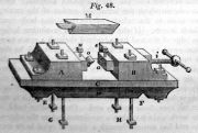
The typical carriage had two main parts, the upper part being arranged to tilt using a jacking screw to alter the tool height. Viewed in plan, the two parts of the carriage were T-shaped castings (or T-shaped on top, and H-shaped below). They were of rather slender width. Modest in thickness (depth), too: having to allow for the thickness of two castings and a gap between them was paid for by the penalty of reduced swing over the carriage. Some makers compensated to some extent by cranking the castings downwards in the middle.
The upper T-shaped carriage casting was the cross-slide. Guidance on the front side relied on small, narrow ridges. These were short and provided very limited transverse movement. This limited the ability to take broad facing cuts without repositioning the tool. The slenderness of the cross-slide also limited its torsional stiffness, important when boring a workpiece with a long overhanging tool.
Rapid adjustment of tool height seemed to be more important than rigidity on US lathes, and the concept seems so fraught with drawbacks that there must be more behind it than meets the eye of the 21st century observer. A possible explanation is offered here [42], which suggests that for several decades lathe operators in the USA were disadvantaged in the availability of satisfactory steel lathe tools. The US tools would have demanded more frequent reshaping and regrinding, making quick adjustment desirable.
Moving now to the headstocks and tailstocks, these were broad for stability, but the wide span between the support feet - often exacerbated by having four slender legs and small feet - caused another loss of rigidity. The feet were presumably small in order to minimise the amount of chipping and filing.
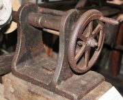
The carriage was moved along the bed by a chain or by a moving rack. The chain was powered from the lathe spindle via gearing or moved manually using a large handwheel located alongside the headstock.
Worm and wheel gearing was provided to drive the chain wheel, typically having two worms, one above and one below the wheel. The worm shafts were interconnected by a frame, which when raised or lowered would engage one or other worm (or neither), to drive the chain in either direction. An alternative reversing arrangement used a cluster of three bevel gears.
It might seem that the fixed position of the handwheel would be very inconvenient when the carriage was not near the headstock. And so it was: Many of us still remember the old chain-feed lathe with the big pilot wheel at the headstock which had to be turned to feed the carriage. 'Chordal' used to say that when a man was using such a lathe to square up an end of a shaft, he would run up to the headstock, yank the handwheel, and run back to see what happened.[43]
Chain drive is by no means ideal for moving the carriage, and some lathes used a moving rack drive as an alternative. This was probably welcomed by operators, but such lathes demanded more space, as the rack was attached to the carriage and protruded beyond the bed when the carriage approached the headstock.
Not all of these lathes had a chain or a moving rack. One old example featured in 'Machinery' in 1897 had a fixed rack, whose teeth were cast integral with one of the guides fixed to the wooden bed.[44]. When seen by the author of the article, the carriage was positioned using a crowbar, but then it was only being used for facing the ends of iron columns. He could only assume that it was originally moved by a ratchet wrench acting on a pinion on the carriage. It had an authenticated history going back to 1832, 'at which time it had already seen a number of years of service'. Over 65 years old, and still earning its crust.
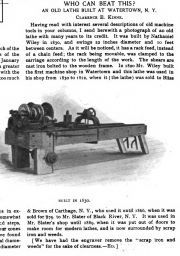
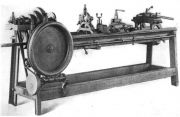
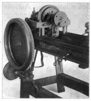
Examples of these old lathes were often featured in US production engineering magazines. Their date of construction was often speculative, but an example built by Nathaniel Wiley at Watertown seems to have been positively dated to 1830.[45]. It had several owners before being put out to grass in 1889. See photo above (the large handwheel is missing).
A well-preserved example is described and illustrated here[46] and here [47]. It has been attributed to Moore and Colby, evidently between 1833 and 1837. It has a rack feed, and each beam of its bed is laminated from eight pine boards. An iron weight of >150 lbs hung from the carriage. Interestingly, the lathe had a leadscrew, although it is not clear how this was accommodated.
A rack-type lathe having a stamped date of 1833 and the engraved initials N.M. is shown in detail here [48]. Back gear was added to theheadstock at some later date.
Joseph Wickham Roe[49] is strangely quiet on the matter of this type of American lathe. The sole relevant mention is in reference to machines from one maker, Samuel Flagg, whose lathes are described as 'light and crude, with a wooden bed, wrought-iron strips for ways, chain-operated carriage, and cast gears.....'.
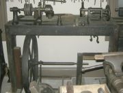
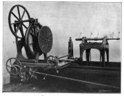
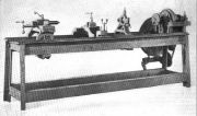
Those 'light and crude' American lathes must have demanded heroic efforts from their operators to produce good work. A particularly character-building example at the works of Kilbourn & Lincoln in Fall River, was described and illustrated in the American Machinist in 1913 [50]. See photo above. The author states that it was probably bought by Mr Lincoln when he started in business in Fall River in 1829. However, although he arrived in Fall River in 1829, in 1831 he was employed at the Massassoit Mill[51], opening the 1829 date to further doubt.
Mr E. A. Dixie, an entertaining contributor of articles on early machine tools to the American Machinist, described a lathe built by Baxter D. Whitney in 1834, when Whitney was just 17.[52]. See photos. The lathe remained in use for over 60 years, no doubt challenging the patience of generations of turners. It had the typical shortcomings described above, including a rather slender wooden bed. The article also described and illustrated a later lathe designed by Whitney, which had a number of improvements, including a leadscrew. The author makes some interesting observations on the measurement standards applicable in the works of Baxter D. Whitney & Son in the 1880s, as related to him by a foreman, Mr. Sawyer.
The operator's life would have been made easier by the addition of a compound slide, but these are absent from known examples of early American lathes.
The persistence of this type of light construction may, in part, reflect transportation difficulties. The purchaser could presumably buy a set of metal parts, and then provide his own wooden bed, perhaps to be assembled by a journeyman from the factory. The heaviest individual part may have been the low-tech weight hung from the carriage! The survival of many of these old lathes is a tribute to the quality of the wood and its seasoning.
Several of the surviving examples of these early lathes were made with cast iron beds. Comparison of the rest of the equipment leaves no doubt that they were contemporary with their early wooden-bed counterparts. An example was rescued in 2012 and restored by Bruce E. Babcock in Ohio. He reported his findings in detail in a masterly series of posts in the Practical Machinist forum [53]. He also found a similar lathe in Moffett Mill, Lincoln, RI, which could well be from the same maker.
Despite their shortcomings, that type of lathe held sway in the USA for many years and often gave many decades of service, but eventually gave way to machines of much more rational design, having iron beds with efficiently-disposed material. The headstocks and tailstocks were also made stiffer. The V-guides for the carriage were made less acute, with separate guides provided for the tailstock. For some reason, the V guides were usually in pairs, rather than having the kinematic pairing of a single V and a flat way. Leadscrews and/or layshafts replaced chains or moving racks. However, some makers still persisted with the rise-and-fall carriage with its hanging weight. For example, see the Lathe and Morse lathe here. Some others who retained the rise-and-fall carriage abandoned the weight in favour of additional guides on the bed and 'fingers' on the carriage to prevent lifting. See here for an excellent account of the restoration of a Putnam lathe of c.1870[54]. Although this is outside the timescale of 'early lathes', it does show how the old concept was updated and considerably improved.
The widespread adoption and long production period of these lathes is curious, given the remarkably innovative and user-focused machine tools that would later emerge from the USA. Some, at least, or the shortcomings of those lathes can be explained by difficulties in sourcing or producing materials and components, particularly large bed castings, leadscrews, and planed surfaces. A surprising limitation was the availability of steel for the working parts, even in the mid 19thC. See Freeland Tool Works (USA) regarding steel-clad wrought iron lathe spindles.
The family resemblance of these lathes suggests a common parent. Who was that parent? Robert S. Woodbury in his 'History of the Lathe to 1850'[55] highlights just one US maker, David Wilkinson, who designed a lathe that 'came into very wide use, especially in the government arsenals', and added that 'we can be sure that by 1806 David Wilkinson, acting independently, had finally constructed a general purpose lathe with a screw drive of its carriage and suitable for extensive industrial use.' What happened to these lathes, or even illustrations of them? With screw-drive carriages, they were evidently not the lathes discussed above, which were notable for having their carriages positioned by chains or racks, not by leadscrews.
Our view of the design of these lathes should be tempered by recognition of their date of construction. Unfortunately, although we know that the type was still in production in the 1840s, there is a surprising lack of reliable early dates for them. If they were available in, say, the 1820s, they would have represented a great advance on the alternative, i.e. hand lathes. In the UK, although we know that slide lathes were used widely in the 1820s, and that superior lathes were available from makers including Roberts, Fox and others, we do not know much about the adequacy of the lesser-known makes of slide lathes available in the average UK machine shop at that time.
Early Design Features, and the Problem of Dating
As previously stated, there are many lathes in preservation whose makers and dates of construction are completely unknown. We can identify certain features on different lathes which have common design features, and hope that dating information will eventually be found which will at least allow a specific era to be assigned.
The photographs on this page include examples of some primitive lathes. These may well be very old, but on the other hand their simple construction may reflect a lack of facilities available to the maker, or lack of knowledge of the 'state of the art'. The lack of dating knowledge discourages attempts to present these in chronological order, as will become apparent.
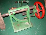
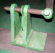
A particularly primitive example can be seen at Combe Mill (see photo). Its maker minimised the amount of metal, and the number of screwed fasteners. The adjustable wooden headstock and tailstock are fixed in place by wooden wedges. One minor detail which is common to many early lathes is the shape of the head on the tailstock centre's screw. The head is forged with 14 facets, a shape commonly produced by blacksmiths, perhaps over a very long period.
A drawing of lathe produced by 1809 by Charles Williams, brass valve maker of Southwark, shows a number of bolt heads of this 14-faceted shape (see illustration). This lathe also shows a cast iron headstock typical of many early lathes, having a conical main bearing, with a pointed centre supporting the outboard end of the spindle and taking the thrust force. The illustration here is dated 1814, but another version was included in a communication from Williams dated 5 January 1810 (hence the basis for saying that the lathe was in use by 1809)[56]
The same type of faceted screw head can be on the tailstock of the lathe at Cotehele Mill (see photo), and can be seen in drawings of the c.1794 Joseph Bramah lathe.
Despite the lack of dating evidence, it is clear from their characteristics that some of the surviving early lathes with iron headstocks and tailstocks date from the late 18th century. We can find examples of such lathes in contemporary adverts. For example, in 1791 textile machine maker Joseph Owen (Manchester) was advertising the sale of 'An Iron Lathe, with Iron Headstocks, a Foot Wheel, &c. Also a Wood Lathe, with very strong Iron Work, capable of turning a Pully, 16 Inches Diameter, with a large Wheel.'[57]
Mention has already been made of the typical headstock design, having a tapered main bearing at the 'chuck' end, and a pointed screw to support the outboard end of the spindle and to take the thrust. An alternative arrangement had a horizontally split main bearing. Beyond this there was little scope for varying the headstock design of early lathes.
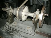
The tailstock, however, offered more scope for variety. Tailstocks were also known as 'loose headstocks', poppets, or puppets. On Maudslay's tailstocks, the barrel (spindle) was pushed towards the workpiece by a forcing screw, but the screw did not withdraw the barrel. Others had a screwed spindle, while many had an indirect-acting screw, as seen in the photo of the lathe. Examples can be seen on the lathes at Tiverton Museum (see photos). It is quite possible that some of these date from the late 18thC. However, the use of handwheels might well represent a later date, despite the otherwise archaic appearance of the tailstock. Of course, a screw with a handwheel might be a later replacement for the original. The two larger tailstocks at Tiverton show a typical arrangement for locking the barrel, using a sort of eyebolt through which the barrel passed.
A common feature on early lathes was the provision of a square tapered hole in the headstock and tailstock spindle to hold a centre, driving prong, or drill.
A lathe on display at Beamish Museum is said to have been used by George Stephenson in 1818. Its tailstock probably represents the next phase of development from the early type seen at Tiverton Museum. More difficult to make, assuming that the hole for the barrel was bored for a reasonable length. The headstock is unusual for the time, having split bearings at both front and rear, the front bearing presumably taking the thrust load.
The Museum of Bath at Work has a fine collection of old lathes, and the first of the Bath photos shows a step forward in development. The wooden bed is clad with iron, and although the headstock and tailstock design is still basically the same, the detailed design and quality are clearly improved from the earlier examples.
When the Soho Foundry, established by Boulton and Watt, closed in 1895, the technical press took considerable interest in the ancient machine tools. Mention was made of lathes whose spindle was driven by worm and wheel, the wheel having wooden teeth. 'Several of them are more than eighty years old, and nothing can exceed the sweetness and beauty of their motion. The wooden cogs are lubricated with blacklead and tallow ...... There is a certain amount of elasticity provided which totally eliminates back-lash and "dither", and we are told that one of these lathes of great age will turn out long piston-rods much better in every respect than any but the highest class of modern lathe.'[58]. 1895 Photograph of a large lathe set up to turn a heavy workpiece here.[59]
Published Histories of Lathe Development
A number of accounts of machine tool development have been published. Most display good standards of objectivity, but all reveal some nationalistic bias, which is partly understandable in view of the accessibility of material to the authors at the place and time they were writing.
The writer of a brief article 'The History of the Lathe' in The Engineer observed that it was 'very remarkable how little has been done with reference to the history of lathes and other machine tools.'[60]
A number of good books were published in English in the 1960s, written by Robert S. Woodbury, L T C Rolt, and W. Steeds. Prior to this the best known work had been written by Joseph W. Roe.
Woodbury provided a generally excellent review illustrating how many of the key features of 19th century industrial lathes were anticipated in special-purpose lathes during previous centuries.[61] He credits Henry Maudslay as a man of genius who synthesised the key elements when the time was right for the birth of the industrial cutting lathe. A less satisfactory aspect is the credit he gives to David Wilkinson in developing heavy general purpose industrial lathes, which he stated came into very wide industrial use, and 'would feel familiar to a modern machinist', yet he offers no illustration or detailed description. In contrast, while accepting that Maudslay built many precision lathes, he questions whether he had built a 'precision lathe of industrial size', writing 'But where is the evidence? Where are pictures, drawings, or descriptions of these machines?' He didn't have far to look: the Henry Ford Museum has a 'c.1804' Maudslay industrial lathe (see Henry_Maudslay:_Machine_Tools), and photographs of lathes in Maudslay's Lambeth works appeared in 'Engineering', 18 January 1901.
Early Versatile Lathes
Early lathe users were aware that a lathe could be used for much more than turning and boring cylindrical work. By facing the end of a workpiece using the cross slide, a reasonably plane surface could be produced (in fact the cross slide of later lathes was normally set slightly off square from the lathe axis, so as to cut a slightly recessed surface). By repositioning the workpiece in the chuck or on the faceplate, other faces could be machined flat. Or the workpiece could be bolted to the cross slide, and faced using a flycutter or milling-type cutter.
No specific examples have so far been identified of lathes designed for facing flat surfaces before the 19th century. Such machines must have been used, however, for example to machine discs and wheels for scientific instruments (for dividing engines, for example).
From c.1820 Johnson Jex was using his special lathe to produce a wide range of shapes.
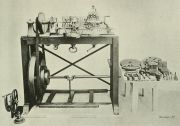
Joseph Clement adapted a treadle lathe for Charles Babbage. A description and photograph appeared in 'Machinery' in 1909, and the photograph is reproduced here [62]. Photo reproduced above. It shows an auxiliary bed with a compound slide mounted on the main bed. It could be driven by gears from the spindle. Components were added by Clement between 1824 and 1830 which made the lathe very versatile, including the ability to do milling work. Flycutters and a facing mill with inserted cutters can be seen on the table in the photo. The lathe has been preserved. Photograph here [63]
This 1895 photograph, taken at the Soho Foundry of Boulton and Watt prior to the sale of the works, shows what is clearly an early lathe with a compound slide. Another photograph here, taken at the same place and time, shows what appears to be a similar lathe with a milling attachment. In fact, the resemblance seems only to extend to the bolted-on legs, and it is not a lathe. It has an unusual two-piece headstock, but the headstock spindle is not driven. Rather, it is indexed round by a worm and wheel to present the workpiece to the milling cutter at the required angle. The milling attachment is of interest. If it was as old as the rest of the machine, then it would certainly be classed as an early milling machine. The milling head was fed automatically by means of an eccentric rod driven from the spindle. The two-piece headstock possibly reflects triangular bar bed lathe practice.
Vertical Lathes
Lathes having a vertical axis offer certain advantages, particularly when setting up and machining components whose diameter is relatively large and the length relatively short. Nowadays these machines are more commonly known as vertical boring mills or vertical turning lathes.
An early example was used by, and probably made by, Fenton and Murray of Leeds. When Simon Goodrich visited their works in March 1830 he recorded in his notebook: 'Observed their mode of turning rams for hydraulic pumps by an upright lathe. Mr Jackson says that they turn them so true and fit so well even without leather [that?] the ram is supported for [? minutes?] by the [air?] in the cylinder.'[64]
Fales and Jenks in the USA made a special purpose vertical lathe, possibly as early as 1833.
Bodmer patented a machine in 1839 which he described as a circular planer, as it could oscillate to machine sectors, as well as complete circles.
Turret Lathes
Turret lathes and other advanced types such as automatic lathes are arguably outside the timescale of this review of 'early' lathes, so just a brief overview will be offered. Turret lathes originated in the USA and represented a completely new departure in lathe design. The first examples are believed to have been designed by Stephen Fitch, Frederick W. Howe or Elisha K. Root between 1840 and 1850. Turret lathes allowed a variety of profiles to be machined on short components by semi-skilled or unskilled operators without removing the component from the chuck. This was achieved by having a selection of tools for surfacing, chamfering, drilling, boring, threading, etc., arranged sequentially on a holder (turret) which indexed round. The principle was straightforward, but much ingenuity and high standards of accuracy were needed in the design and construction.
An example made by E. K. Root at the Colt Armory was featured in [65] in 1896. Its light construction suggests an early date.[66]
The Surprising Persistence of Hand Turning
An article in the 'American Machinist' in 1908, written by James Lomas of Manchester, revealed the surprising information that hand turning was still widely used in Lancashire and Yorkshire, particularly in the large scale production of textile machinery. The author described the ability of experienced turners to produce a high standard of finish by hand turning, and cited the ability to rapidly machine a variety of surfaces on a component without resorting to turret lathes equipped with a range of tools. He also noted the ability to get a hand tool into awkward locations without the constraints of a bulky carriage. Interesting observations are also made on the simplicity of the drive arrangements on hand lathes, conducive to rapid production (although not to safety)[67]
See Also
Sources of Information
- ↑ 'Henry Maudslay & The Pioneers of the Machine Age' edited by John Cantrell and Gillian Cookson, Tempus Publishing, 2002
- ↑ [1] Science Museum Group - 1805 1805 drawing of treenail and coak making lathe, from Simon Goodrich archive
- ↑ Derby Mercury - 18 January 1787]
- ↑ Chester Chronicle - Friday 19 March 1790
- ↑ [2] Wikipedia for Jan Verbruggen
- ↑ Manchester Mercury, 4 November 1800
- ↑ Manchester Mercury, 21 September 1802
- ↑ Manchester Mercury, 9 November 1802
- ↑ Manchester Mercury, 3 July 1804
- ↑ Manchester Mercury - Tuesday 25 September 1804
- ↑ Manchester Mercury - Tuesday 26 March 1805
- ↑ Manchester Mercury, 6 August 1805
- ↑ Morning Advertiser, 14 February 1806
- ↑ Manchester Mercury, 25 February 1806
- ↑ Paper presented to the Newcomen Society by E A Forward in 1937, entitled 'Simon Goodrich and his Work as an Engineer - Compiled from his Journals and Memoranda'.
- ↑ Manchester Mercury - Tuesday 28 June 1808
- ↑ Manchester Mercury, 31 January 1809
- ↑ [3] Deutsches Museum - Die historischen Werkzeug-Maschinen
- ↑ Salisbury and Winchester Journal - 31 July 1775
- ↑ [4] Science Museum:
- ↑ Hampshire Chronicle, 16 January 1796
- ↑ Newcastle Courant, 27 May 1738
- ↑ [5] The Miscellaneous Papers of John Smeaton, Civil Engineer, &c. F.R.S, by John Smeaton, 1814
- ↑ [6] Observations on the graduation of astronomical instruments; with an explanation of the method invented by the late Mr. Henry Hindley, of York, clock-maker, to divide circles into any given number of parts, by John Smeaton, communicated by Henry Cavendish, read 17 November 1785: 47 page pdf, Royal Society
- ↑ R R Angerstein's Illustrated Travel Diary 1753-1755: industry in England and Wales from a Swedish perspective, translated by Torsten & Peter Berg, The Science Museum, London 2001, p.334 and footnotes 274-6
- ↑ Newcastle Courant - Saturday 29 September 1764
- ↑ [7] 'Titles of patents of invention, chronologically arranged covers period from Mar. 2, 1617 to Oct. 1, 1852' by Bennet Woodcroft, 1854
- ↑ The British Cyclopaedia, Vol 2, by Charles F. Partington, 1835: Engraving of Ramsden's first lathe for cutting 'endless screws' for his circular dividing engine
- ↑ Hereford Journal, 7 July 1785
- ↑ 'The Cabinet Cyclopaedia' Vol II by Dionysius Lardner, London, 1833, p.142 ff.
- ↑ [8] Encylopaedia Metropolitana, Vol VIII, 1845
- ↑ [9] 'Turning and Mechanical Manipulation' Vol 2, by Charles Holtzapffel, 1856
- ↑ 'James Watt and the Steam Engine' by H W Dickinson & R Jenkins, 1927, p.265
- ↑ 'James Watt and the Steam Engine' by H W Dickinson & R Jenkins, 1927, p.276
- ↑ A Treatise on the Steam Engine - Historical, Practical and Descriptive (1827) Volume 2, by John Farey. David & Charles, 1972
- ↑ Manchester Mercury - Tuesday 15 December 1795
- ↑ [10] American Machinist, 24 Sept 1903
- ↑ 'Tools for the Job' by L T C Rolt, HMSO, 1986
- ↑ [11] American Machinist, 1 June 1899, pp.478-480
- ↑ [12] Machinery, Aug 1911, pp.972-3: 'Hard vs soft cast-iron ways for machine tools' by Robert Grimshaw
- ↑ [13] 'American Machinist', 23 Jan 1896, pp.107-8
- ↑ [14] Practical Machinist forum: post by 'Joe in NH', 16 Feb 2016
- ↑ [15] American Machinist, Vol 41, 1914, p.1150
- ↑ [16] Machinery, Dec 1897, pp.109 &
- ↑ [17] Machinery, November 1897, p.83
- ↑ [18] vintagemachinery.org
- ↑ [19] Practical Machinist forum - post by 'Humphrey Machine 2014
- ↑ [20] Post in the Practical Machinist website by 'enginebill', July 2018
- ↑ 'English & American Tool Builders' by Joseph Wickham Roe, 1916.
- ↑ [21] American Machinist, 1 May 1913
- ↑ [22] Fall River Branch of the Lincoln Family: Updated: February 11, 2017. Genealogy, Massachusetts Genealogy
- ↑ [23] American Machinist, 27 February 1908, pp.317-320
- ↑ [24] Practical Machinist, 'Early Lathe in a Corn Field
- ↑ [25] Practical Machinist forum: 'The Putnam comes home, started by Ray B. Marlow
- ↑ 'History of the Lathe to 1850' by Robert S. Woodbury, Society for the History of Technology, Cleveland, Ohio, 1961
- ↑ [26] Transactions of the Society for the Encouragement of Arts, .... Vol. XXVIII 1810, p.196ff
- ↑ Manchester Mercury - Tuesday 28 June 1791
- ↑ [27] The Engineer, 27 Sept 1895, p.305
- ↑ [28] Library of Birmingham, Birmingham Images, Soho Foundry Erecting Shop
- ↑ [29] The Engineer, 18 Oct 1895
- ↑ [30] 'History of the Lathe to 1850' by Robert S. Woodbury, Society for the History of Technology, Cleveland, Ohio, 1961
- ↑ [31] Machinery, September 1909, pp.3-4
- ↑ [32] 'Cambridge Computing: 75 Years' by Haroon Ahmed, 2013. Cambridge Computer Laboratory and Third Millennium Publishing Ltd
- ↑ 'Matthew Murray 1765-1826 and the firm of Fenton Murray and Co 1795-1844' by Paul Murray Thompson, published by Paul Murray Thompson, 2015; p.298. Note: the author leaves the square brackets empty.
- ↑ Machinery
- ↑ [33] Machinery, Aug 1896, p.365
- ↑ [34] American Machinist, Vol 31 Part 1, 18 June 1908, pp.938-940


