Blaauwkrantz Bridge


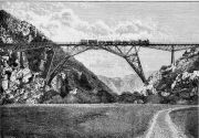
Blaauwkrantz Bridge, Makhanda (Grahamstown) district, Eastern Cape, South Africa
The bridge was of unusual design, financed by Firbank, Pauling and Co or by George Craig Sanders Pauling.
Designer: Max am Ende of Westminster.
Ironwork constructed by Andrew Handyside and Co of Derby.
The bridge was constructed in 1883-4. Demolished in 1928 and replaced by a new one.[1]
Scene of the in 1911 Blaauwkrantz Bridge Disaster[2]
See here for an excellent series of photographs taken during and after construction, and also shortly after the 1911 derailment accident.
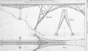
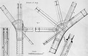
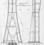
Some details of the 1883/4 bridge from a US Consular report, which described it as 'fine structure': The rails were 165 ft above the low water level (185 ft above the Kowie River bed). The braced arch was splayed out to a width of 61 ft 6" from centre to centre of the girders at springing, and rested on four hinged joints fixed to masonry. The width gradually reduced to 14 ft 9". The braced piers resembled trestles. [3]
From 'History of Bridge Engineering', 1911
'M. Max Ende, and R. E. Cooper, 1884, designed the Blaauw Krantz viaduct [drawing omitted] over a ravine at Cape Colony, Africa, which has a center 230-foot opening of very unusual form. The two truss frames are united at the middle but at the ends they separate to bear on four individual masonry pedestals. The designer states that "while the plan has quite an uncouth appearance on paper, the bridge is imposing when observed from underneath." In any case the design shows much originality.'[4]
Description in The Engineer
The design and construction of the bridge were described by the designer, Max am Ende, in a series of three articles in The Engineer in 1885. From Part I[5]:-
'The viaduct is built over a rocky ravine on the railway from Port Alfred to Grahamstown, at a height of about 200ft. from the bottom. Its length is 480ft. 6in., and the width of the platform is 15 ft., the gauge of the railway being 3ft. 6in. The central span of the viaduct is an arch of 220ft. span between abutments and about 90 ft. height; the remainder of the space on each side is divided into two spans by an iron pier at a distance of 68ft. from the retaining wall. These piers are 36ft. 2in. high and carry girders 144ft. long, balanced each on a pivot in the centre. One end of these girders is secured to the retaining walls by means of horizontal and vertical anchorages, while the other end rests in a sliding bearing on the top flange of the arch.
' In designing the structure the following points had to be considered:
1. That, on account of the great height above the ground, and on account of the high price of timber at the site, the structure could be easily erected without the use of scaffolding supporting it as a whole.
2. That, on account of the high freights to Port Alfred, the quantity of iron in the structure should be as small as possible.
3. That the single parts of the principal span should be easy to lift, and that there should be as few of them as possible. For this latter reason most of them were made in lengths of 20 ft. and more. The question of economy
of material presented itself as a comparison between a few
standard types, viz., the girder bridge of small independent
spans; the cantilever bridge or the continuous girder bndge in three large spans ; the single girder bridge with one
large span and several small spans; and the arch with small
girder spans on each side. The suspension bridge was left
out of question as inadmissible. A girder bridge with
small independent spans on rocker piers would pro bably
have been the most economical, even taking into account
the great height of the piers near the middle of the ravine,
but there would have been some difficulty in holding those
piers in position until they could be secured to the girders
at the top; and, moreover, such a structure would have
been strikingly out of harmony with the character of the
site. On the other hand , a cantilever or continuous girder
bridge in three spans - although such structures have been
erected in similar localities - could not enter into comparison of simple economy of material , because such a
design would entirely disregard the anomaly that the
greater part of the structure, viz., the side spans, being
necessarily constructed to carry across a large space,
would be too near the ground to justify the omission of
further supports. The question was, therefore, narrowed
to a comparison between the present arch and a central
independent girder of the same span, including the piers
on which it rests. The small side spans could obviously
be left out in each case. The comparison was made with
a view not only to arrive at a decision in this particular
case, but also of answering the question of the economy
of the arch more generally. The following table contains
the weights of geometrically similar structures of three
different spans, of which the second is the one here
described. The so-called theoretical weight is that which
the structure would have if no part required stiffening,
leaving out also all connections and all wind bracing. The
moving load is taken at one ton per foot lineal, and the
strain on the iron at an average of four tons per square
inch. The proportion of the girder is taken at 1 in 8.
[Table omitted]
'It can be seen from these results that the economical advantage of the arch increases with the span. In small arches this advantage would not be large enough to counterbalance the greater cost of manufacture; but in the arch of 220 ft. span the advantage is already very marked. If the table were continued, it would show that the girder, even if the platform were artificially widened, would become impossible at a point where the arch can still be made without difficulty. The calculations leading to the above results would occupy too much space to make it desirable on this occasion to produce them, and it will be necessary to resume the description of the viaduct, two views of which, taken from photographs, will be found on page 165.'
From Part II [6] :-
'The girders on each side of the arch were used during the erection as cranes for lifting and erecting those parts of the arch, which are necessary to form a support for the overhanging ends of the girders. A connection was then effected by means of horizontal bolts with adjusting screws, and the remaining parts of the arch were erected according to the projecting method. A pivot was inserted at the crown, and there was also a pivot at each abutment of the arch, so that when the adjusting screws were loosened the central span became an arch with three hinges, and for the time being quite independent, as the girders did not press upon it either vertically or horizontally. The strains in the whole structure could not be determined, for although the arch was afterwards transformed into one without hinges, and the strains from loads subsequently brought upon it became dependent upon the elasticity of the structure, the usual uncertainty as to the strains in such cases could be entirely obviated, because the transformation was effected without adding any fresh strains - i.e., the former condition did not transfer any uncertainty to the latter.
[Details of the calculation method followed].
Part III of the article [7] contains further information on the calculations, description and illustrations of the erection method, and information on the site testing.
See Also
Sources of Information
- ↑ [1] artefacts.co.za website: Blaauwkrantz Bridge
- ↑ [2] The Heritage Portal: The Blaauwkrantz Bridge Disaster
- ↑ [3] Commercial Relations of the United States: Reports from the Consuls of the United States .... No. 49, January 1885 by United States Bureau of Foreign Commerce
- ↑ [4] 'History of Bridge Engineering' by Henry Grattan Tyrrell, 1911, pp.363-4
- ↑ The Engineer 1885/02/27
- ↑ The Engineer 1885/03/13
- ↑ The Engineer 1885/04/17

