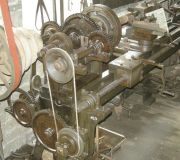
Fox of Derby: Lathe at Wortley Top Forge


Note: This is a sub-section of Fox of Derby
See photographs. This is described as 'c.1820', and it came from the machine shop at Milford Mill, Derbyshire, which was built in 1817. Along with the Fox of Derby: Lathe in Birmingham, the lathe was used in the construction and maintenance of textile machinery. They were driven by a waterwheel, and the date 1817 appears on the cast-iron beams and line-shafting brackets of the building that was evidently built to house them.
This lathe, with its rigid box bed, separate shafts for the self-acting surfacing and screwcutting functions, tapered spindle bearings, and ten speeds, is remarkably advanced for its age.
Details
Photo 4: The design of the tailstock is generally well thought out. It can be moved along the bed by a hand-cranked pinion. Provision is made for offsetting the centre for taper turning. The only shortcoming is that the barrel can only be moved forward by the forcing screw, and has to be pushed back after releasing the screw.
The horizontal rod in photo 7 moves a lever to engage one or other of the bevel gears, to engage clockwise or antic-clockwise rotation of the square layshaft which drive the worm and wheel to move the lathe's carriage.
Photo 6 shows the carriage (saddle) and toolpost, and the large wormwheel which turns a pinion engaging with the cast iron rack to traverse the carriage. An important feature of the carriage is the extent to which the 'wings' extend forward, providing excellent support when the toolpost is close up to the headstock (the slideways for the carriage extend all the way to the end of the bed). The box connected to the corner of the carriage nearest the camera evidently contains a split nut to engage the leadscrew for screwcutting. To the right of this box is a hand crank. Its spindle entends across the bed, where a pinion engages with the rack, just visible in the photo. The spindle protrudes on the other side, where a large gear wheel is attached. It slides on a feather (elongated key) to engage with a worm, seen in photos 7 & 8. Photo 9 shows how the gear is moved inwards and outwards by a lever.
Photo 8: The worm travels with the carriage, sliding along the square layshaft.
Photo 11: In the left foreground is a cluster of five pulleys which drive the input shaft. It will be seen that two gears engage with the main spindle. They are keyed to both shaft such that they can be engaged and disengaged to give high and low speed ranges, giving a total of 10 spindle speeds.

