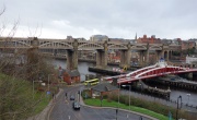
High Level Bridge, Newcastle


The High Level Bridge is a road and railway bridge spanning the River Tyne between Newcastle upon Tyne and Gateshead in North East England.
A prospectus of a High Level Bridge Company was issued in 1843; George Stephenson and George Hudson were members of the committee of management and Robert Stephenson was the consulting engineer. The project was eventually taken up by the Newcastle and Darlington Railway Co, and an act for the construction of the bridge was obtained in 1845.
Designed by Robert Stephenson and T. E. Harrison and built between 1847 and 1849, the High Level Bridge is a wrought and cast iron tied arch or bow-string girder bridge. It is a fine and long standing engineering solution to a difficult problem; the spanning of 1,337 feet of river valley, including 512 feet across water.
The High Level Bridge has six river spans of 125 feet length, sitting on masonry piers 46 by 16 feet in section and up to 131 feet height. There are also four land spans on each side, of 36 feet 3 inches.
The single carriageway road and pedestrian walkways occupy the lower deck of the spans, 85 feet above the high water mark, and the railway upper deck 112 feet above the high water mark. The total weight of the structure is 5,000 tons.
1848 The opening ceremony took place, hosted by the York, Newcastle and Berwick Railway Company[1]
According to a contemporary encyclopedia:
'Each river span is crossed by four main cast iron arched ribs, with horizontal tie bars. The roadway is situated between a pair of ribs some 20 feet apart; and walkways are sited on either side of the roadway in a 6 foot gap between the central and outside ribs. The upper, railway, platform, rests on the arches of the ribs, whilst the lower roadway is suspended from the ribs on wrought iron rods. Each arched rib was cast in five sections. Besides the tie-bars, the ribs are braced by horizontal and vertical bracing frames, while diagonal bracings are inserted in the spandrels, or spaces between the arches and the girders which carry the railway. On the tops of the spandrel pillars, girders extend length-wise, from which other stretch at right-angles across the arched ribs. The whole thus has a perfectly rigid character and is found to bear the heaviest weights without deflection.'
The bridge was built for the York, Newcastle and Berwick Railway, and together with Stephenson's Royal Border Bridge at Berwick upon Tweed, completed the line of a London-Edinburgh railway nowadays known as the East Coast Main Line. The bridge was opened to rail traffic, without ceremony, on 15 August 1849. It was officially opened on 27 September 1849 by Queen Victoria; and brought into ordinary use on 4 February 1850.
The total cost of the bridge was £491,153, broken down as follows: The bridge proper cost £243,096, including £112,000 for the metal work, for which Messrs Hawks, Crawshay and Sons were the main contractors, with much ironwork coming from subcontractors. The approaches to the bridge cost £113,057, and land and compensation - including to the 650 Newcastle and 130 Gateshead families who were relocated to enable its construction - £135,000. Rush and Lawton were the civil works contractors.
There were also competing plans - not taken forward - for a low level bridge; in 1836 Richard Grainger with engineer Thomas Sopwith proposed a crossing 20 feet (6.1 m) above high-water mark, running the Newcastle & Carlisle, Great North of England and Brandling Junction railways into a low level terminus. Under their plans, the Scotland railway would follow contour lines to the east and north, whilst the Carlisle line would be taken up inclined planes.
Stephenson's High Level Bridge was designed after, but completed before his equally innovative Britannia Bridge (constructed 1846-50) over the Menai Strait, and was said to have influenced Isambard Kingdom Brunel in his design of the Royal Albert Bridge (1855; constructed 1859) across the River Tamar at Saltash.
The High Level Bridge began to vibrate like a piece of thin wire, but provided an excellent vantage point for the Great fire of Newcastle and Gateshead in 1854.
In 1906, construction of the King Edward VII Bridge, some 500 yards to the west of the High Level Bridge, was completed. This second bridge addressed the central operational weakness of the single bridge, which was that trains entering the station from the south had to be reversed back across the bridge when returning in that direction. It also meant that locomotives had to switch ends before a train could head north towards Edinburgh.
Since the newer bridge opened, the High Level no longer forms part of the East Coast Main Line. Instead, it provides a route for trains going towards Sunderland, Middlesbrough and, formerly, the Leamside Line. It is also occasionally used for London trains wanting to turn around as the two bridges are linked on the Gateshead side to form a loop. For this reason, the western track across the bridge is electrified.
Over its long life, the condition of the bridge has deteriorated, and loading has markedly increased. Strengthening and remedial work has been carried out at various times, most recently in 2005-8. The need to strengthen and repair the bridge without spoiling the historic character of the bridge has posed many challenges. A great deal of ingenuity has been needed to come up with solutions which retain the original structural elements as far as possible, and which are discrete and capable of being installed around those structures.
Aspects of Design
There a six main spans. Each span has four cast iron arches. These are 3 ft 6" deep at the crown, increasing to 3 ft 9" at the ends. The flanges are 12" wide. The rise of the arch is 17 ft 6". Each arch is assembled from five castings, bolted together (see photos 16 & 17). The arch castings were produced by John Abbot and Co[2]
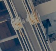
The 'strings' to the bow comprise chains of flat wrought iron plate links, visible from below the bridge (see photos 21-25). The chain links are 1" thick and 7" deep. The pins are 3½" diameter.
Between the rail deck and the road deck there are vertical cast iron columns. The portion of the columns above the arch takes the compressive loading from the rail deck to the arch. Although the columns appear at first sight to be continuous from beneath the rail deck down to the road deck, and to be integral with the arch castings, they are in fact divided. It would have been unwise to attempt to cast the whole of the columns integral with the arch castings, so only a portion of each column is integral with the arch. The portions are butted together, more or less discretely. The position of joints in a number of columns is marked by arrows in photo 26.
The road deck is supported from the arches by hangers (tiebars, suspension rods). The original hangers were round wrought iron bars concealed within the square columns. Additional exposed steel hangers were installed in the 1920s. They were attached to the arches and to the cast iron longitudinal road deck beams by bent steel plate clips. In 2005-8, major changes were made, such that the lower ends of the hangers are no longer attached to the cast iron beam, but to new short steel beams located above the old beams. These new beams have brackets which extend downwards to support the deck beams. The hangers can be seen in photos 16-19, with their attachment clips bolted to the webs of the arch girders.
Cross-bracing of considerable stiffness is provided between the pairs of arches (see photos 9, 11, 12, 13, 23). The challenges in designing these interconnecting frames, and fitting them, would have been immense, and are a great tribute to the draughtsmen, foundrymen, machinists and fitters. Each of the individual frames had to be made so as to be in good contact with its neighbours and with the arches. The difficulties can perhaps be appreciated by reference to photos 11-13. Study of the way in which every component of this inflexible structure fits neatly with its neighbours hints at the unsung skills of those involved.
The designers succeeded in combining function with aesthetics, producing an elegant structure without the excessive ornamentation of later Victorian bridges. This can be seen to advantage in photo 27.
See Also
Sources of Information
- [2] Wikipedia

