Parsons Turbines: Early Examples


This is a sub-section of Charles Algernon Parsons
Note: Although attention is focused on the steam turbines, Parsons also applied his ingenuity to the generators, control systems, condensers and other ancillary equipment, propellers and hull design. The turbine-generator ancillary systems will reward study of examples in museums.
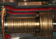
Charles Parsons' first 'compound steam turbine' produced 10 HP at 18,000 rpm. The blades were straight and sharpened at the leading edge. In order to avoid a nett thrust load on the shaft, steam was admitted at the mid length and expanded in two directions through 'mirror image' sets of blades. A degree of elasticity was provided in the bearings to allow the rotor to rotate about its dynamic axis. This 1884 machine is on display at the London Science Museum
1883 Charles Parsons had become a junior partner at Clarke, Chapman and Co, Gateshead, in charge of the new electrical department. By 1888 about 200 of their turbine generators were in service, mainly for lighting on ships. The partnership was dissolved and he left in 1889 to found C. A. Parsons and Co at Heaton, Newcastle.
Parsons was debarred from using the patents he had taken out while working with Clarke, Chapman. These patents covered axial flow turbines, so he set about developing radial flow turbines[2], and these were produced until he regained the rights to build axial flow turbines in 1894.
Early Speed Governing System
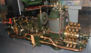
On the earliest Parsons turbines, speed was controlled by a governor which worked on a vacuum system, the partial vacuum being created by a simple shaft-driven centrifugal fan. The sub-atmospheric pressure acted on a spring-loaded leather diaphragm, which altered the opening of the steam admission (throttle) valve. The arrangement can be seen in the photos of the early turbines.
The air pump impeller (fan) was simply a disc with drilled radial holes communicating with axial holes. The hub of the disc ran within the bearing pedestal, so that air was drawn out of the pedestal. See cross-sectional arragement drawing above (1888). The perforated periphery of the fan is visible in several of the photos.
Advantage was taken of the sub-atmospheric pressure in the pedestal for priming the oilpump.
Later, an additional device was introduced to modulate the vacuum, and hence the speed, according to the output voltage of the generator. The field from the magnets of the dynamo determined the position of a pivoting, spring-loaded soft iron bar. In moving, the end of the bar affected the opening of a port connected the the governing vacuum pipe, altering the pressure and hence the speed. See photo of Clarke, Chapman, Parsons turbine.
Movement of the pivoted iron bar was resisted by a coil spring. The torsional resistance could be increased by 'winding up' the spring. On the example in the Deutsches Museum a mall worm and wheel drive was provided for this purpose (just visible in last photo of the 1889 turbine).
'Gust' Governing
This vacuum system was replaced by 'gust' governing, patented in 1890. Here, the turbines used steam pressure to open the steam admission valve. The steam pressure acted on the underside of a spring-loaded piston fixed to the steam valve's spindle, the pressure under the piston being controlled by a relay arrangement. The relay's pilot valve was positioned by a lever controlled by a speed governor and by an electrical solenoid.
Parsons' aim was to maximise efficiency at part load by avoiding continuous throttling of the steam supplied to the first stage nozzles. Another benefit of this oscillation was that it minimised the risk of the steam valve sticking and hence causing 'hunting' or - far worse - failure to limit the speed.
Parsons caused the high pressure steam to be admitted intermittently - in 'gusts'. This was initally achieved by making the double-beat steam valve oscillate continuously. The oscillating movement was given to the valve relay's operating arm by a worm-driven eccentric. These features can be seen in some of the sectioned turbines in the photographs. Later, solenoids provided the oscillation.
See Also
Sources of Information
- ↑ Engineering 1888/01/13
- ↑ 'Early Days of the Power Station Industry' by R H Parsons, 1939

