

General
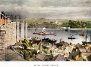
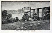
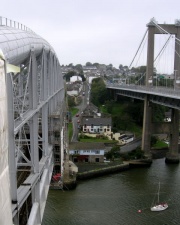
The Royal Albert Bridge (also known as The Tamar Bridge) spans the River Tamar between Plymouth, on the Devon bank, and Saltash on the Cornish bank.
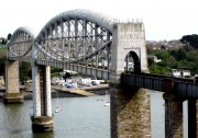
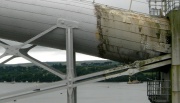
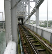
It has been described as a bowstring suspension bridge, and its unique design consists of two 455 feet lenticular iron trusses 100 feet above the water, with conventional plate-girder approach spans. This gives it a total length of 2,187.5 feet. It carries the Cornish Main Line railway in and out of Cornwall.
It was designed by Isambard Kingdom Brunel.
Surveying started in 1848 and construction commenced in 1854.
The first main span was positioned in 1857 and the completed bridge was opened by Prince Albert on 2 May 1859. Brunel died later that year and his name was then placed above the portals at either end of the bridge as a memorial. Work was carried out during the twentieth century to replace the approach spans and strengthen the main spans.
Background
Two rival schemes for a railway to Falmouth, Cornwall were proposed in the 1830s. The 'central' scheme was a route from Exeter around the north of Dartmoor, an easy route to construct but with little intermediate traffic. The other, the 'coastal' scheme, was a line with many engineering difficulties but which could serve the important naval town of Plymouth and the industrial area around St Austell.
The central scheme was backed by the London and South Western Railway while the coastal scheme was supported by the Cornwall Railway and backed by the Great Western Railway which wanted it to join up with the South Devon Railway at Devonport.
The Cornwall Railway applied for an Act of Parliament in 1845 but it was rejected, in part because of the plan of William Scarth Moorsom to carry trains across the water of the Hamoaze on the Torpoint Ferry.
Following this Isambard Kingdom Brunel took over as engineer and proposed to cross the water higher upsteam at Saltash. The Act enabling this scheme was passed on 3 August 1846.
The structure was the third in a series of three large wrought iron bridges built in the middle of the nineteenth century and was influenced by the preceding two, both of which had been designed by Robert Stephenson. The two central sections of Brunel's bridge are novel adaptations of the design Stephenson employed for the High Level Bridge across the River Tyne in Newcastle Upon Tyne in 1849.
Brunel was present when Stephenson raised the girders of his Britannia Bridge across the Menai Strait in the same year.
From 1849 to 1853 was Brunel erecting an iron bridge of his own. The Chepstow Railway Bridge carried the South Wales Railway across the River Wye and featured a main truss of 300 feet with a curving tubular main member, and three conventional plate-girder approach spans of 100 feet, a similar solution to that adopted for crossing the River Tamar at Saltash.
The river is around 1,100 feet wide at Saltash. Brunel's first thoughts had been to cross this on a timber viaduct with a central span of 255 feet and six approach spans of 105 feet with 80 feet clearance above the water. This was rejected by the Admiralty, who had statutory responsibility for navigable waters, and Brunel thus produced a design to give 100 feet clearance, with two spans of 300 feet and two of 200 feet.
The final design as built consists of two main iron spans of 455 feet with 100 feet clearance above mean high spring tide.
There are also seventeen much shorter and more conventional plate-girder approach spans on the shore. On the Cornish side there are ten which measure a total length for the nineteen spans of 2,187.5 feet.
Preliminary Work
We tend to judge a bridge by the end result, and are impressed or otherwise by its appearance and its magnitude. We tend not to appreciate the difficulties faced by the designers and constructors, for example in surveying, specifying the precise spans and elevations. Perhaps the least-appreciated aspect is the challenge of specifying and constructing the piers and abutments. In the case of the Royal Albert Bridge, the work involved in establishing the central pier is particularly interesting.
The Cornwall Railway at this time was finding it difficult to raise funds and so most operations were suspended that summer, but a small fund was allowed for Brunel to continue the survey. The cylinder was positioned at 35 different places and a total of 175 borings made over an area 50 feet square.
In 1853 the tenders for the bridge were considered by the Cornwall Railway Board, and it was decided to let the work to Charles Mare, a shipbuilder from Blackwall who had built the ironwork for the Britannia Bridge. The fee he sought for building the Saltash Bridge was £162,000, but on 21 September 1855 he filed for bankruptcy.
Brunel proposed that the company should take over the works on the bridge without engaging another contractor, to which the company agreed.
Mare's first task had been to establish an erecting yard on the Devon shore with a jetty and workshops. He then proceeded to construct the 'Great Cylinder' (see below).
The Central Pier
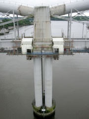
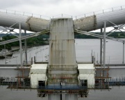
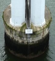
Brunel was faced with the major difficulty of designing and constructing the central pier. Its masonry column was to be 35 ft diameter and 96 ft high from the bedrock foundation to its upper surface above normal high water level. Above this were to be four octagonal cast iron columns, 100 ft high, surmounted by the 50 ft high central portal of the bridge.
Basically, it was to be a tower, nearly 200 ft high, in the middle of a deep tidal estuary.
The solution was very different to that adopted a few years earlier for the Chepstow Railway Bridge, where the equivalent to the central pier had to be founded on rock 84 ft below high water level. At Chepstow this pier comprised a cluster of ten concrete-filled cast cylindrical columns.
The work at Saltash is well described and illustrated by John Binding[1] and by Sir Hubert-Shirley-Smith[2], who both draw on a paper by Robert Pearson Brereton[3] and the subsequent discussion record (part copy here). Additional information was provided by I. K. Brunel's son, Isambard Brunel[4].
Isambard Brunel wrote in 1870 that 'The centre pier of the Saltash bridge is, like many great engineering works, out of sight, and liitle regarded by any but professional men.'
6 ft Diameter Cylinder
The first work was to properly survey the river bed in the vicinity of the proposed centre pier. Brunel designed a 6 feet diameter iron cylinder 85 feet tall, slung between two gun-brig hulks, from which it could be lowered and raised using winches. It was launched into the Tamar on 26 April 1848. From the bottom of this the bed of the river could be examined to identify its nature and the location of solid foundations, the mud at the bottom providing an effective seal. William Glennie was in control of the operations.
The 6 ft diameter cylinder was assembled by riveting together wrought iron plates. To accommodate the external pressure of the water, the thickness of the plates increased from top 3/8" to 3/4" at the bottom. Due to limitations in the size of rolled wrought iron plates at the time, the available width reduced from 2 ft 8½" at the top to 1 ft 5½" at the bottom.
On completion of the survey, the cylinder was incorporated in the 'Great Cylinder'.
The Great Cylinder
This was an iron cylinder approximately 37 feet in diameter, 90 feet tall, which was to serve as a coffer dam, and as a caisson if need be, for the construction of the central pier. Isambard Brunel recalled that two decades earlier, while working on the Thames Tunnel, I. K. Brunel had conceived the idea of working under a diving bell of large dimensions, but he did not pursue it into practice because Lord Cochrane had taken out a patent for a similar idea. However the idea was revived, and it was decided that the Great Cylinder would embody the diving bell concept in case the cylinder could not be used solely as a coffer dam. Brunel Jr's statement may give the impression that the concept was held in abeyance until used at Saltash, but this far from being the case the case. Jacques Triger in France had used pneumatic caissons for sinking shafts in waterlogged ground in the early 1840s. William Bush patented a similar method in 1841, and applied it at Goodwin Sands. About the same time, Laurence Holker Potts patented a method of sinking cylinders by evacuating them. This was applied for several bridges, and in 1851 it was adopted for the piers of Rochester Bridge. However Potts' method failed at Rochester due to submerged obstacles, and the resident engineer, John D'Urban Hughes, then applied the idea of using pneumatic pressure, with air locks, to allow men to work in the cylinders. In an 1851 Paper, Hughes reported that he only became aware of Triger's Process after his equipment had been constructed and was in the process of being installed ar Rochester. Shortly afterwards Hughes was employed by Brunel at Chepstow, and later at Saltash[5]
The Great Cylinder was launched in May 1854 and moored at the planned position in the centre of the river between four pontoons, an impressive acheivement. The bottom had been shaped to follow the rock surveyed in 1848; in fact the bottom edge was 6ft deeper to the south west. Once it was settled on the river bed the water was pumped out, the mud within it excavated, and a solid masonry pier built up clear of the water. This was completed in November 1856.
The cylinder was remarkable in conception and in its design and construction. The bottom was provided with a cutting edge. A wrought iron dome was provided about 20 ft above the bottom, and this was pierced by a 10 ft diameter central tube. The 6 ft tube was set within this, offset to one side. The tubes projected several feet below the dome and connected with conical-topped inner chamber. This inner chamber and the outer cylinder provided an annular space about 4 ft wide. The space could be pressurised with air for men to work in preparing the foundation and building a ring of masonry. Brunel credited Robert Pearson Brereton with the idea of the annulus, which avoided the need to pressurised the whole area of the cylinder. The air-jacket was about 4 feet wide, divided into eleven compartments, and connected with the bottom of the 6 ft diameter cylinder by an air passage below the dome. It was intended that the lower part of the cylinder, below the ground, should be filled in with solid masonry, and that it should not be withdrawn. The upper part, 50 feet high, was constructed in two pieces of larger diameter than the masonry, with vertical separating joints bolted together, capable of being removed after the completion of the pier.
Pneumatic apparatus and air pumps, previously used at the Chepstow Railway Bridge, were fixed to the top of the 6ft cylinder; two engines of 10 HP were placed upon the upper deck to work the air pumps, and two 13" water pumps were fixed inside the 10ft cylinder.
Based on the results of the exploratory boring, it had been hoped that the mud would provide adequate sealing to allow work in the Great Cylinder, without air pressurisation. However this proved not to be the case. The pneumatic system had first to be brought into use when the cylinder tilted during sinking.
Water pumps were used to lower the water inside the 10ft cylinder, thereby reducing the pressure in which the men had to work.
In February 1855, the cylinder was sunk to its full depth, in an upright position ; its bottom being everywhere down to the rock, and 87 feet 6 inches below high water at the lowest place. Before the final dressing of the rock at the bottom, a hemp gasket was worked under the edge of the cylinder, all round the outside, to assist in making it water-tight. The bottom edge on the up and down stream sides, was also secured to the rock, by lewis bolts, to steady it against the action of the current and the tides. In March, the rock was levelled in all the compartments of the air-jacket, and its surface cemented over. The cutting away of the rock was very tedious, as in some parts, as much as 6 feet in depth had to be taken off the hard rock with chisels. between April and May a ring of granite ashlar masonry wasset all round. The granite ring was 4 feet thick, and averaged about 7 feet in height. A bank about 10 feet high, of slag and sand, was thrown round the outside of the cylinder, to compress the mud. The operations with the air-jacket were thus completed, the greatest pressure having been with 86 or 88 feet head of water (about 40 psi). The men suffered from what came to be known as 'caisson sickness' - the bends. Brereton wrote: 'At first some inconvenience [!] was experienced by the men, in working under great pressure, and at the commencement of the work they stayed in too long at one time. He had remained seven hours at the bottom, with some of the men. After coming out they were slightly paralysed, but in two, or three days they, quite recovered. With three-hour shifts, the men could remain at work for several months consecutively.' See 1855 medical article below.
Even without the problem of the bends, the working conditions would have been appalling: wet, muddy, cramped, and illuminated only by candles, and the work would have often been difficult and dispiriting, for example shovelling mud, chiselling hard rock, laying heavy granite blocks in confined spaces. In addition, there were the effects on the body of working in compressed air. There were also the potential for the atmosphere to become fouled by build-up of carbon dioxide (depending on the air inlet and exhaust method), increased smokiness of candles in dense air, and release of gases from mud and even from concrete.
In June 1855 it was thought that pressurised operations were complete, and water was pumped out of the space below the dome, and removal of mud commenced. However a leak arose, and extra pumps had to be obtained, and more material deposited round the base of the cylinder. By November it had been decided that the space would have to be pressurised with air. Unfortunately the 10 ft tube was not designed for the pressure, and a thicker 9 ft tube, about 50 ft long, was made and 'slipped' into the 10 ft tube after removing the 6 ft tube. Extra air pumps, and air locks were obtained for the 9 ft cylinder. The cylinder was shored by diametral struts. Another problem to be addressed was buoyancy of the 290-ton Great Cylinder when the water was pumped out. To counteract this, about 350 tons of iron ballast, was placed on shelves near the top, and 400 tons of iron and sand on top of the dome. Removal of mud began in December, and the masonry work commenced in early January 1856. Lewis bolts were let into the rock, with iron bars let into the masonry, to further secure the 10 ft cylinder in case of further influx of water. Brereton described further progress, involving water leakage collection arrangements, masonry (granite, hard bricks, concrete, sheet piling). The ironwork was progressively removed as the masonry was built up (easier said than done, as the rivet heads would have to be chiselled off and the rivets drifted out). By early April the masonry had reached the base of the dome, which was then cut away. Nevertheless, continuous pumping was required until the middle of June, when the masonry height was 46 ft. The masonry was completed by the end of October. The upper part of the cylinder was removed in two halves and taken away by the pontoons (the cylinder was constructed in two halves, having a bolted vertical joint).
Considerable difficulty arose with maintaining the required air pressure, due to a variety of problems, including leakage past the rivets and caulking of the joints of the relatively thin, large diameter cylinders, and, presumably the flexing action resulting from differential pressure applied cyclically.
Construction
The landward piers on the Cornish side of the river were completed in 1854 and the girders for these spans were hoisted up to their correct positions. Next to be built was the main truss for the Cornwall side of the river. The lower ties of the trusses formed of chains made from 20 feet links. Many were obtained from the suspended works for Brunel's Clifton Suspension Bridge and others rolled new for Saltash.
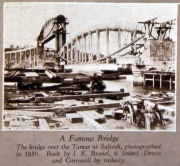
The Cornwall span was floated into position on 1 September 1857 and jacked up to full height in 3 feet stages as the piers were built up beneath it, the central pier using cast iron octagonal columns; the landward one using ordinary masonry.
The second span soon after it was floated onto the piers and had been jacked up the first 12 feet towards its final position. With the yard now cleared of the first truss, work could start on the main Devon span.
This was similarly floated into position on 10 July 1858 and then raised in a similar manner; it was in its final position by 28 December 1858. After this had been removed, part of the yard had to be cleared to allow the construction of the final landward pier and then the Devon approach spans could be raised up to their final position.
The work was sufficiently advanced that directors were able to make an inspection by train on 11 April 1859.
The Cornwall span had been tested before it was launched. The two ends were supported on substantial timber piers and the remaining scaffolding removed. Static loads of 1.25 and then 2.25 tons per foot were placed on the deck, the deflections measured and any permanent change measured once the road was removed. Now that it was completed, the bridge had its statutory inspection and tests by Colonel Yolland on behalf of the Board of Trade on 20 April 1859. He ran a heavy train over the bridge and measured deflections in the main trusses of 1.14 inches (29 mm) in the Devon truss, and 1.20 inches (30 mm) in the Cornwall one. Overall he described it as 'highly satisfactory'.
Opening
1859 Prince Albert had agreed to the bridge being named after him as early as 1853. He was also invited to perform the opening ceremony, and on 2 May 1859 he travelled from Windsor on a special train. Several thousand spectators attended that day, but illness prevented Brunel's attendance, and guests from Cornwall were late for the ceremony as their train broke down at Liskeard. Public services commenced on 4 May 1859.
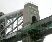
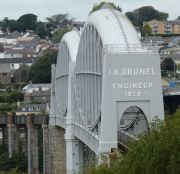
The words I. K. BRUNEL, ENGINEER, 1859 appear in large metal letters on either end of the bridge, added as a memorial after his death on 5 September 1859.
Aspects of Design and Construction
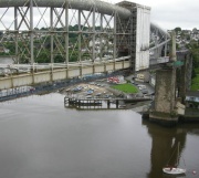
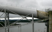
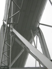
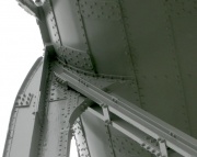
The two large spans have lenticular trusses made of wrought iron. I. K. Brunel's son Isambard Brunel described it 'as a combination of an arch and a suspension bridge, half the weight being placed on the one and half on the other, the outward thrust of the arch .... being counterbalanced by the inward drag of the chains'. The top chord of each truss comprises a large tubular arch in compression, while the bottom chord comprises two tiers of chains of the eyebar type. Each of the trusses is simply supported, and therefore no horizontal thrust is exerted on the piers, which is crucial in view of the curved track on either side. Between these two chords are diagonal cross-bracing members and vertical suspension standards (suspenders) which hang beneath the bottom chord to carry the railway deck's continuous plate beam.
The tubes are elliptical in cross section, 16 ft 9" wide and 12 ft 3" deep. They have logitudinal and circumferential internal stiffeners, and they are considerably stiffened at the ends, the arrangement being concealed within the towers' cast iron cladding. The width of the tube was determined by the width of the single trackway.
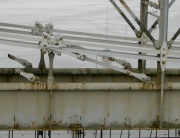
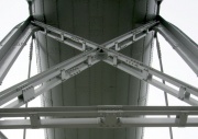
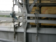
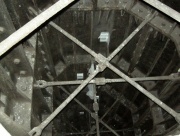
The wrought iron plate deck beams have rounded (semi-circular) top flanges, and slightly dished bottom flanges. Two different arrangements are used to suspend the deck beams. Each of the four deck beams is suspended from the chains (the main eyebars) by ten pin-jointed standards (suspenders), and by eleven rigid standards which cross the chains and extend upwards to connect (by riveted joints) to the large wrought iron compression tubes. Diagonal braces between the suspenders are key to accommodating the dynamic loading in a railway suspension bridge. The diagonal braces are connected by pinned joints near the tops of the suspenders, while the lower end is connected at chain level, rather than close to the deck. Each brace comprised two eyebars, joined by tapered cotters, connected to its neighbour via a central X-shaped gusset plate. The original arrangement at these X-shaped plates was appreciably different to the present arrangement. In the old arrangement each piece of the diagonal brace was a single eye-bar, but now each diagonal eye-bar is assembled from several pieces bolted together, and the connections to the X-plates have wedged pins and a series of six bolts through the X-plates and the eye-bars.
Alterations
In 1921, new access platforms were added that obscured the lettering but in 2006 Network Rail relocated the platforms, allowing the name to be clearly seen again. The walkways had previously been temporarily removed in 1959 and the bridge floodlit during its centenary year.
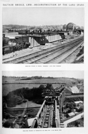
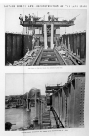
1905 Some 401 new cross-girders were fitted in 1905 to allow heavier locomotives to pass over.
In 1908 the two spans nearest Saltash railway station were replaced with wider ones to accommodate a new track layout.
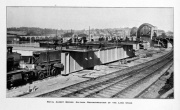
1928/9 The remaining approach spans were replaced on both sides of the river during 1928 and 1929.
During the 1930s new cross-bracing and diagonal sway-bracing members were added between the vertical standards to further strengthen the bridge and keep the suspension chains hanging in the correct shape.
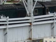
Some of the suspenders suffered from corrosion-related fatigue where they passed between chain links. Temporary repairs were necessary, but modifications were carried out to the deck support arrangements in 1960. Major changes have been made to five of the short suspenders attached to each deck beam, with pin-jointed hangers placed outside the chains. The lower ends were attached to new brackets bolted to the deck beam webs. Three examples can be seen in photo '2023 2'. Note the large size of the centre suspender. The bottom 6 ft of the original suspender was cut off, and a new steel section spliced on.
Following tests in 1966-7, additional diagonal bracing was installed to resist the shearing between the deck and the chains. These braces can be seen in photo '2012 6', but have since been removed.
Items from the Press
1855 'EFFECTS OF SUBMARINE DESCENT. By T. Littleton, M.B., F.R.C.S., of Saltash, Cornwall.
In the progress of constructing an iron bridge across the river Tamar at this place, by Mr. Brunel, attention has been called to certain injuries, sustained by some of workmen engaged therein during the endeavour, which has now proved successful, to procure foundation for the central pier. The absence of any sufficient mention of the kind of accidents which attend upon those conducting submarine occupations, in the notices to which I have been able to gain access, induces me to attempt to supply some of these omissions ; and I trust that the explanation of the effects produced, though far from satisfactory, may be suggestive to those better able to deal with the question, and may by such cooperation ultimately conduce to the welfare of those to whom society owes a debt which it has so long neglected, and which remains for the Committee on Industrial of the Society of Arts to discharge. And to this fully, what better channel of communication and lor assistance can be obtained than that of this journal ? There are accounts given of several the inconveniences which attend in the descent in a diving bell, in the Philosophical Transactions, by Dr. E. Halley and Mr. M. Triewald ; and in Dr. Olinthus Gregory's translation of Abbe Hauy’s Natural Philosophy. Such are the following: a painful sensation of pressure upon the membrana tympani, which soon subsides, the ready communication by the Eustachian tube establishing an equilibrium of pressure on that part; spitting of blood ; bleeding at the nose and ears; bloodshotten state of the eyes ; and the oppressive sensation attendant on confined atmosphere, by which, if the means of constant renewal are not applied, life would be speedily destroyed.
But no allusion is made to one source of danger, that has demanded most attention here ; and which, from the suddenness of the attack, and apprehensions of fatal results attending it, more especially deserves notice.
Some reason for this omission is supplied the difference which the apparatus used here presents from a diving bell, and the less liability to danger which exists in the latter, from the gradual manner in which it is lowered and raised, and the consequently slow increase and diminution of pressure to which its inmates are subjected. Were this, which is so rightly insisted upon by Dr. Halley, were not observed, the same consequences would follow the rapid drawing up of the bell to the surface of water as attend the working in this cylinder, and from the same cause, the sudden removal of pressure. Considering the effects produced on some few by this change, from a pressure of three and half atmospheres (the depth at high spring tides being eighty-five feet) to the normal pressure of fifteen pounds, it is a matter of surprise that more do not suffer them. There have not occurred, so far as I aware, more than half a dozen severe cases, in a work which has occupied daily twenty-five men over a period of many months.
In the severe forms of the attack, the man is taken, within a few minutes after coming out of the cylinder, somewhat as in an apoplectic seizure, with loss of power, preceded by pains, in the lower limbs (paraplegia), as I have seen in two cases, or one-half of the body (hemiplegia) ; another, the only one I have seen so anected, was wholly unconscious, remaining in that state many hours. In those who escape with less injury, their sufferings are in some instances very severe, from pains in the limbs and joints; and few, if any, have wholly escaped these effects at some time or other during the progress of the work. These are evidently the results of pressure on the cerebro-spinal nervous system ; but what are the different links in the chain of causes producing it? It may be, that the respiratory movements are not accompanied by the alternate falling and rising of the brain attending the acts of inspiration and expiration, which undoubtedly constitute important conditions of the brain’s action ; and the impediments occasioned in this respect alone prove obstructive of its functions. I name this as possibly the case, because it is obvious the first few inspiratory efforts, on coming out, from the pressure named, cannot be attended by their ordinary effects, the due influx of venous blood and of atmospheric air into the chest; for the condensed air at that time present in the lungs, and continually brought by the blood of the body, until the whole of it has circulated through the lungs, would expand itself, and thus occupy the space, which under normal conditions the venous blood and atmospheric air would enter the production of the vacuum by inspiration. But more than this must have occurred to bring about such a continuance for weeks of the loss of voluntary power as exists in some these cases. There might have been an extravasation of serum into the ventricles, &c., rupture of small bloodvessels, or possibly, under such physical conditions, there may occur an extrication of air, occasioning pressure on the brain. Under a like series of conditions, Boyle, in his experiments on animals breathing rarefied atmosphere, notices to have manifested itself in the case of a viper — “a conspicuous bubble of air moving to and fro in the humour one of its eyes. — (Phil. Trans., abridged, vol. i., p. 499.).'[6]
We do not know whether Dr Littleton proposed more gradual depressurisation for the workers at Saltash. He was probably not aware of the practice adopted in France at the time. According to an account of given by Pol and Watelle in 1854, men working in a caisson on the banks of the Loire at 3.25 atmospheres were compressed in 15 minutes, worked for a 4 hr. shift, and were — according to the rules — decompressed in 30 minutes.[7]. This was presumably in connection with the process developed by Jacques Triger for sinking shafts in quicksand in connection with mining.
Sale of Construction Equipment, 1859 [8]
'CORNWALL RAILWAY, SALTASH.
To Engineers, Contractors, and Others.
Messrs. FULLER aud HORSEY
Are instructed TO SELL BY AUCTION,
On Tuesday, September 6, and following days, at eleven each day, at the Works, Saltash Bridge, Cornwall, about three miles from Plymouth, and on the banks of the River Tamar,—
THE MACHINERY and TOOLS recently used in the construction of the Royal Albert Bridge, Saltash, including two self-acting planing machines by Glasgow, one to take in 12 feet long by 8 feet wide, the other to take in 12 feet 9 in. long by 3 ft. 3 in. wide; one very powerful self-acting radial drilling machine (radius 11 feet 6 inches) ; a 10-inch self-acting screw-cutting lathe by Smith, Beacock, and Tannett, with 12 feet break ; 14-inch centre sefl-acting screwcutting lathe, by Parr, Curtis, and Madely; a very powerful self-acting double lathe, for facing two surfaces at one operation ; self-acting screw-cutting machine, with taps and dies, to screw up to 2 3/4 inch ; self-acting slotting machine, by Glasgow ; three self-acting wall-drilling machines, two drilling machines, with hand feed motion, one small self-acting planing machine, Glasgow; set of 10 ft. 6 in. plate-bending rolls, four very powerful lever punching and shearing machines, with wrought-iron levers, 11 feet each ; a 15-cwt. Nasmyth’s steam hammer, two 30-inch Lloyd’s fans, wrought iron and wood post cranes ; an hydraulic chain-testing apparatus, with bed 54 feet long, ram and pumps, three high-pressure steam engines, of 8, 12, and 15-horse power, and boilers, two portable steam engines of 10-horse power, by Clayton, Shuttleworth, and Co. ; 200 feet turned bright shafting, 30 riggers, pattern-maker’s lathe, grindstone, large steam winding machine, by Horn; 14 very powerful crabs, stocks, taps, dies, and steel tools, vices, anvils, weighing machines, small fire-engine, and other effects.
To be viewed on Saturday and Monday previous to the Sale (the machinery in motion), when catalogues, at sixpence each, may be had at the Works ; and of Messrs. Fuller and Horsey, Billiter Street, London,
Note.- There is every facility for removal of the goods by either land or water carriage, as there is a jetty with crane for loading on the river, and there is a railway station at Saltash Bridge. The works are also intersected by iron tramways. Freights are very low from Plymouth.
Approved Bills at three months’ date will be taken from purchasers to the extent of £50 and upwards.
The advertisement continued with other plant and surplus material 'remaining from and used in the construction of the Royal Albert Bridge, Saltash, including powerful hydraulic presses used in raising the tubes, 2 with 22-inch rams, and 4 with 10-inch rams, made on an improved principle by Messrs. Easton and Amos, and only used for the tubes ; 2 sets of hydraulic pumps, a very powerful overhead travelling crane. 1 7-ton wharf crane, 2 portable 3-ton cranes on trollies, 13 smiths’ forges, levelling plates, and slabs, a new air machine, 9 ft. 4 in. diameter, 3 atmospheric pumps, (2 by Easton and Amos,) 1000 fathoms chain, 30 pairs sheave blocks, with rope and chain falls snatch blocks, 1000 fathoms rope, 20 tons contractors’ rails, trollies, 20 anchors and kedges, barge, 6 boats, mooring buoys, life buoys, sails and rigging, tarpaulings, ladders, wheeling planks, wheelbarrows, carts. 400 loads squared pine timber in logs, 100 loads cut timber, 500 12-foot planks, pile engines and monkeys, 30 tons bar, rod, and plate iron, 10 tons pig-iron, stores of various descriptions, 20 dozen files, ratchets, smiths’ tools, scales and weights, weighing machines, powerful steelyards, iron and wood tanks, erection of plate furnaces, carpenters’ benches, grindstones, three tons gun metal castings, the temporary erection of boarded enclosures, rafters, joists, slating, brick chimney stacks, and numerous other effects......'
The advertisement continued with the machinery of the saw mills, including a 30 HP horizontal steam engine, two Cornish boilers, four portable engines and boilers, by Clayton and Shuttleworth, 30 circular saws, four large Kyanising tanks, 97 by 12 by 6 ft., a wrought iron cylindrical Burnetizing tank, 75 ft long, 6 ft diameter, with pressurising pump, etc.
See Also
Sources of Information
- ↑ 'Brunel's Royal Albert Bridge' by John Binding, Twelveheads Press, Truro, 1997
- ↑ 'Royal Albert Bridge, Saltash' by Sir Hubert-Shirley-Smith, chapter VIII in The Works of Isambard Kingdom Brunel - an Engineering Appreciation' Edited by Sir Alfred Pugsley, I.C.E. & University of Bristol, 1976
- ↑ [1] Description of the Centre Pier of the Saltash Bridge, on the Cornwall Railway, and of the means employed for its Construction." by Robert Pearson Brereton, M. Inst. C.E.
- ↑ 'The Life of Isambard Kingdom Brunel - Civil Engineer' by Isambard Brunel, 1870
- ↑ [2] I.C.E. Obituary of John D'Urban Hughes
- ↑ Dublin Medical Press - Wednesday 21 February 1855
- ↑ [3] CAISSON ILLNESS AND DIVER'S PALSY. AN EXPERIMENTAL STUDY. By LEONARD HILL, M.B., E.R.S., and J. J. R. MACLEOD, M.B. 1903
- ↑ Gloucester Journal - Saturday 27 August 1859
- 'Brunel's Royal Albert Bridge' by John Binding, Twelveheads Press, Truro, 1997. This is a superb source of information on the design and construction of the bridge.
- [4] Wikipedia

