Tone Aqueduct


near Wellington, Somerset
Built c.1830 to carry the Grand Western Canal over the River Tone.
This aqueduct deserves more prominence in the history of iron bridges.
Seen from the former canal towpath, this appears at first sight to be a masonry aqueduct lined with an iron trough. Viewed from the River Tone, we see a cast iron aqueduct flanked by two masonry arches. See Figs. 1 and 2. Fig. 2 shows one end of the 30 ft span iron aqueduct supported by dressed masonry blocks, flanked by a masonry arch on each side.
In fact, close scrutiny reveals a surprising form of construction, in which the masonry arches provide support to the iron channel. This will be discussed further, after describing the unusual method of assembly of the iron components.
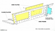
In most early cast iron aqueducts the side walls consist of flanged plates bolted to each other at their vertical flanges. See, for example, Edstone Aqueduct. However on the Tone Aqueduct the side panels are not bolted to each other, but instead they are bolted to side frames. See sketch, Fig. 5. A similar principle is used on the nearby Nynehead Aqueduct. As far as is known, this form of construction is unique to these two aqueducts.
Each side frame is assembled from three castings, connected to each other by sloping bolted flanges. Sandwiched between each of these sloping flanges is a cast iron plate which protrudes about 2 ft into the masonry arch. The angle of slope would be expected to match the angle of the voussoirs of the arch at this position, but this has not been confirmed (voussoirs being the wedge-shaped stone blocks of the arch). Thus any deflection of the iron duct will be resisted by compression of the masonry arch against which these plates press.
The cast iron side plates are about ¾" thick. The abutting edges located at mid span are vertical. The next edges are splayed, while the next joints, nearest the abutments, are partly splayed and partly vertical (see Fig. 6).
The floor of the trough is assembled from cast iron plates. These are flanged and bolted to each other and to the side frames. They are also supported by a lip at the bottom of the side frame. The floor plates' flanges are at the top, i.e. under water, while the underside is flat.
Although not obvious in its overgrown state, the aqueduct is designed with a slight skew to suit the angle of the approaching river to the line of the canal. Consequently the left and right iron sides walls of the aqueduct are offset relative to each other, and also the floor plates are not quite rectangular, but parallelogram-shaped.
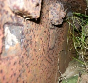
The side plates are attached to the frames by bolts, whose square heads are flush in countersunk holes. See Fig. 4. The floor castings are fixed with conventional bolts having (shallow) square heads.
The top of the side plates has a small lip which sits on top of the side frame. This presumably helped during assembly.
How, What, Why, Who?
The side frames were cast in closed moulds. The inner face of some of the side plates has an appearance typical of being cast in an open mould, with pores and 'waves' (Fig. 4). However, with open moulds, we expect to see a square edge along the top surface of the casting, whereas here the upper edge of the plates is bull-nosed (see Fig. 7). Perhaps the edge was rounded to reduce the risk of damage to boat's hulls. In fact there is clear evidence that some, if not all, of the side plates were cast in closed moulds.
Having stated that the main structure of the iron aqueduct consists of side frames with plates bolted thereto, and flanged plates bolted at the bottom of the duct, there are several more features to mention. The first is a short (2 ft. long) bolted extension at each end of the side walls, in the form of an iron casting with flanges. For some reason the top edge of the casting is not rounded off like the main side plates. Instead it has a separate rounded strip riveted or screwed to the casting. One of these castings lies displaced, presumably having been forced out by a growing tree. A nearby side plate had fractured, and this has been skilfully weld-repaired. Otherwise, the visible parts of the ironwork appear to be in remarkably good condition. The spalled masonry voussoirs seen in Fig. 1 are not representative of the condition elsewhere.
The adjacent edges of the ends of the side plates do not butt against each other. Fig. 4 shows that there is a narrow strip, presumably of wrought iron, in the gap. It may be something to do with sealing the joint. The method of fixing the strip has not been identified.
The method of construction must have posed problems for the workshop when it came to making the bolt holes in the side frames. The square, tapered holes in the side plates would have been produced using cores in the foundry mould. However, it has not been established how the corresponding holes in the side frame could have been postioned to align with the side plates' holes (note that the spacing of the holes in the side plates is somewhat wayward). Later practice would involve spotting through to the frames from the side plates and then drilling. To explore this possibility would require removal of one of the bolts. The prospect of drilling so many holes in cast iron with c.1830 equipment was not to be relished. In fact the prospect is so daunting that it is probable that the holes were, in fact, cast in. If so, this probably involved making thin wooden templates to establish the location of each hole, and transfering these locations to the moulds for both the side plates and the frames. Individual cores would than have been fixed at these locations in the moulds.
There are some small square headed bolts (Fig. 8) and filled square holes (Fig. 9) whose role has not been identified.
The engineer for the Grand Western Canal was James Green. There seems little doubt that he was responsible for the design of the aqueduct.
The foundry which produced the iron castings has not been identified. We know that James Green had his own workshops in Exeter, but a brief sale notice (1837) made no reference to foundry equipment, although it did include foundry patterns for aqueducts.
Another of James Green's aqueducts can be seen a short distance away. This is of much shorter span, with the emphasis of visual appeal, but uses similar design principles. See Nynehead Aqueduct.

