Transporter Bridge, Newport


The Newport Transporter Bridge crosses the River Usk in Newport, South Wales.
History
Designed by French engineer Ferdinand Arnodin, in conjunction with Robert Henry Haynes. It was built between 1902 and 1906 and opened by Godfrey Charles Morgan, 1st Viscount Tredegar on 12 September 1906. Contractor: Alfred Thorne and Sons.
A transporter bridge was chosen because the river banks are very low at the desired crossing point (a few miles south of the city centre) where an ordinary bridge would need a very long approach ramp to attain sufficient height to allow ships to pass under, and a ferry could not be used during low tide at the site. The Newport Harbour Commissioners had sent a deputation to study the Rouen Transporter Bridge in August 1899[1]
The steelwork was supplied by the Cleveland Bridge and Engineering Co; the cables were furnished by W. B. Brown and Co., of Liverpool. The contractor for the supply and installation of the electrical apparatus was R. W. Blackwell, Limited, of Westminster. The DC drive motors were made by Lancashire Dynamo and Crypto.
The height of the towers is 242 feet and the height of the horizontal beam above the road is 177 feet. The transporter platform or gondola travels the 645 feet between the towers at ten feet (three metres) per second, propelled by a wire rope.
Design
The design was described in detail in The Engineer in 1906[2].
The design principles are typical of several of Arnodin's transporter bridges. The main span (the boom, or stiffening girder) is supported by a combination of suspension cables and oblique cable stays. Comparison with a typical suspension bridge shows significant similarities and also appreciable differences. Because of the great height of the towers, the anchor points for the suspension cables had to be set back much further inland from the river bank than would otherwise be the case. The boom assembly has no deck as such - its primary role is to support the rails for the gondola carriage's wheels. The absence of a solid deck greatly reduces the potential for problems due to aerodynamic forces. The magnitude and location of the service load on a transporter bridge is determined by the size and local position of the gondola, whereas the load on a suspension road bridge is much less determinate.
The boom's girder construction is particularly interesting, having the characteristics of a Whipple truss. In fact in some respects the construction has more in common with the rigging of biplane wings than with typical truss girder bridges! See 1906 drawing (Fig 3) and 2014 photo (Fig 4) above. The upper horizontal member of the boom (the upper chord) is assembled from steel channels arranged thus: ] [ with flat plates riveted across the top and bottom. The lower chord of the boom is, in essence, an I-beam.
Between the top and bottom chords is a series of vertical struts. These struts can only act purely in compression, the top and bottom ends being forked, the forks straddling horizontal pins located in lugs in the top and bottom beams. Compression forces are applied by the girders' diagonal members - the 'X-bracing'. These are ties, acting purely in tension. In fact they are cables. The cable ends are attached by U-bolts to the aforementioned pins in the top and bottom chords. These same pins also provide attachment points for the main diagonal stays and the vertical suspension cables. The loading from the carriage wheels and from the boom anchorage cables, are all applied through the bottom chord.
Fig 3 shows that adjacent X-braces overlap, so the number of vertical struts and diagonal ties is doubled-up compared with some (or all?) of Arnodin's other transporter bridge girder designs. Also, the use of cables for the diagonal ties is unusual. Steel bars have been used for the reconstructed Rochefort Transporter Bridge, and were also used on the Rouen Transporter Bridge, and perhaps others.
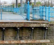
Fig 4 shows a number of features of interest, including the bottom chord of the boom, which is an I-beam fabricated by riveting together steel plate and angle sections. The carriage wheels run on rail lines bolted to the top of the bottom flange on each side. The bottom of a vertical strut (compression membe) is also shown. Its forked end (not visible) is sitting on top of the pin which is located in angle iron brackets riveted to the top flange of the I-beam. Also note how the diagonal cable is attached to the pin by a pair of U-bolts.
The top chords of the booms are braced together transversely by a number of horizontal steel beams and by a larger number of diagonal angle iron braces. See Figs 5 and 6. Similar bracing was not used at Rouen or Rochefort, but it is apparent that the Newport booms are appreciably deeper, at 4 m, so it may be that the bracing was considered necessary to avoid buckling of the top boom.
Fig 9 shows a degree of permanent set in the chords of the boom, perhaps suggesting that design margins were not over-generous.
Fig 10 shows the eight suspension cables on one side of the bridge. Each vertical suspension rod hangs from a horizontal bar supported by groups of four suspension cables. The bar's U-bolts only serve as hangers: they do not clamp the bar to the cables, although it may be that the bars are clamped on the steeper part of the catenary cable. In order to avoid point contact between the U-bolts and the wires, small steel saddles have been locally clipped to the cables. Some or all of these saddles incorporate stops to prevent the hangers slipping down the cables.
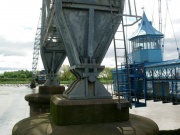
Unusually for suspension bridges, they are not continuous from anchorage to anchorage. Instead, the catenary cables meet the anchorage cables at the saddles on top of each pylon, where U-bolts attach them to a common horizontal pin. See Fig 7.
Fig 11 shows part of a layout drawing by F. Arnodin, on display at Tredegar House. It shows the cable stays radiating from the top of the pylons, and the vertical suspenders descending from the main suspension cables. Also note the appreciable length of the carriage (32 m) compared with the length of the gondola. It has 15 pairs of wheels on each side. The boom is cantilevered outboard of the pylons to accommodate the length of the carriage. This is shown in Fig 12, where the attachment of the cable stays to pins on the bottom chord will be noted. Note, too, the corroded tie cables. Evidently they were not galvanized.
It appears that the booms are not fixed directly to the pylons, all the support and restraint coming from the cable stays, suspension cables, and boom anchorage cables.
Arnodin designed his transporter bridges to be maintainable. This philosophy allowed for the replacement of all the various cables on the Newport bridge at various times. The main suspension cables were replaced in a programme carried out in 1992-5.[3]
See here for the findings of a recent analysis to compare and contrast the design and behaviour of the Newport and the Middlesbrough Transporter Bridge. [4]
NOTE: Some of the statements about the design of the bridge are somewhat speculative. Grace's Guide welcomes any corrections.
Historical Context
Only twenty large transporter bridges were built worldwide, and only 8 or 9 have survived. Five of the twenty were built in accordance with Palacio and Arnodin's 1887 patent, and of these five, Newport is the only example not to have undergone significant structural alteration in its lifetime. Justification and clarification of these statements follows.
The primary source consulted for the number and type of these bridges is Transporter Bridges - an Illustrated History by John Hannavy. He provides information on the bridges at Vizcaya, Bizerte/Brest, Rouen, Rochefort and Newport for which Arnodin was the sole or joint designer and which incorporate the key features shown in the 1887 patent. Arnodin also designed the transporter bridges at Nantes and Marseille, but these are structurally very different, being of the double-cantilevered type, and no longer exist. The Vizcaya bridge was rebuilt as a suspension bridge as distinct from a combined suspension and cable-stayed bridge, and with a boom constructed entirely from steel sections, instead of Arnodin's combination of steel sections and cable or rod ties. The Rochefort bridge had been rebuilt in the 1930s with a plate girder boom, but an enlightened approach led to it being recently rebuilt with a boom structure more in accordance with the original design, albeit with significant differences.
Access
The bridge has much to offer has a tourist attraction. It has widespread appeal as an imposing structure and, when reopened, as a high level viewing platform. It is also provides a rare opportunity to experience an unusual form of transport - referred to in the 19th century as an 'aerial ferry'. For anyone interested in structural engineering, it will provide a superb opportunity to closely study one of the few survivors of Arnodin's suspension-type transporter bridges.
The bridge is closed until Spring 2023 for restoration and for the construction of a new visitor centre. See website [4] for more information. Before the start of this work, following the 1990s restoration, the bridge carried vehicles and pedestrians. For a small fee, visitors could climb the stairs and walk across the main span, and return the same way or descend and return on the gondola. This was an excellent opportunity, subject to the weather and various other constraints (including the ability to climb 270 steps and walk across the floor gratings!).
See Also
- For photographs of the bridge in modern times see [5]
Sources of Information
- ↑ South Wales Weekly Argus and Monmouthshire Advertiser - Saturday 12 August 1899
- ↑ [1] The Engineer, 14 Sept 1906, p.264ff.
- ↑ [2] 'Newport Transporter Bridge — an historical perspective' by Barry Mawson and Robert Lark of Cardiff University, January 2000 ICE Proceedings Civil Engineering 138(1):40-48
- ↑ [3] Wind loads on open truss structures: applications of blockage to historic transporter bridges by A. J. Carter, P. H. Taylor, H. Santo, A. Blakeborough. Published:19 August 2019
- [6] Wikipedia

